Disassembly, maintenance and assembly of reducer of bridge crane
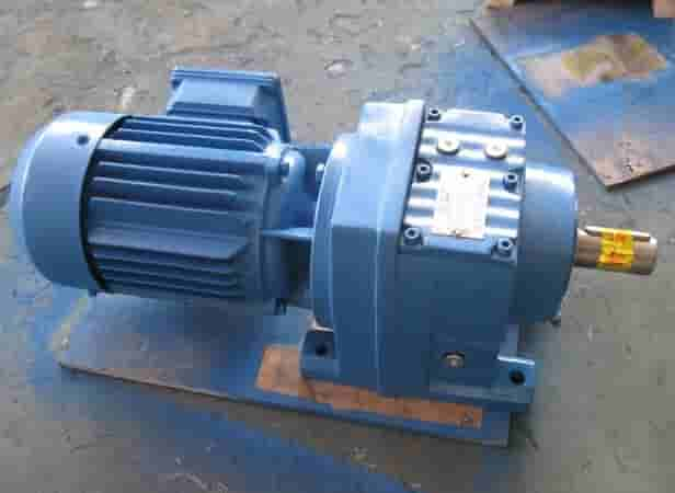
The reducer is an indispensable mechanical part of the bridge crane . It can adjust the motor speed to an appropriate speed and increase the power torque to provide greater power for the operation of the crane truck and trolley. The editor introduces the disassembly, maintenance and assembly of the reducer of the lower bridge crane.
(1) Removal of reducer
- Disassembly of the entire reducer If there are spare parts for the reducer of the same model and transmission ratio, the damaged reducer can be replaced as a whole. Remove the connecting bolts at the high-speed shaft end and the driven shaft end of the reducer respectively to separate the reducer from the transmission system. After removing the anchor bolts, the entire reducer can be removed.
- Disassembly of reducer parts
- Remove the coupling connecting bolts of the coupling between the high-speed shaft end and the driven shaft end, so that the reducer is disconnected from the transmission system.
- Remove the connecting bolts between the upper cover of the reducer and the base, tighten the cover screw, and lift the upper cover of the reducer to make the split joint surface of the reducer have a gap, which is convenient for prying and remove the upper cover of the reducer.
- Take out the drive shaft assembly and the driven shaft assembly of the reducer from the base of the reducer respectively.
(2) Overhaul of reducer
- Inspection and repair of the joint surface of the reducer case: After a period of operation of the reducer, the case sometimes deforms. The deformation of the joint surface of the box body not only affects the transmission accuracy of the gear, but also causes oil leakage. Therefore, it must be repaired.
- Use kerosene to clean the box body, clean the dirt and sludge on the joint surface, apply red lead oil to make the two joint surfaces run in, scrape off individual high points and burrs after each grinding, after several grindings, the requirements can be achieved Accuracy.
- After grinding, a feeler gauge can be used to check the gap of the joint surface, and its value should not exceed 0.03mm, and the parallelism error between the bottom surface and the joint surface should not exceed 0.5mm within a length of 1m.
- Overhaul of gears
- Check the pitting condition of the gear tooth surface. When the fatigue pitting area exceeds 50% along the tooth height and tooth width, it shall be scrapped.
- Check the wear condition of the gear tooth surface. After the gear is worn, the tooth thickness will become thinner and the strength will decrease. To ensure safety, gears that exceed the aforementioned obsolete standards are allowed to be used after removing the burrs on the tooth end with a whetstone or a scraper.
- Maintenance of shaft
- Use a 20x magnifying glass to check the shaft for cracks, and replace it immediately if the cracks are found.
- The allowable radial runout of the gear shaft is no more than 0.02~0.03mm, and the straightness error of the transmission shaft is no more than 0.5mm. When the straightness of the shaft exceeds this value, cold or hot correction (flame correction) should be carried out.
- Inspection and repair of oil leakage
- Oil leakage of
- reducer oil leakage of reducer usually occurs in the following places:
- a. The joint surface of the reducer box, especially the vertical reducer, is particularly serious.
- b. The shaft end cover of each shaft of the reducer, especially the shaft hole of the through cover.
- c. The flat cover of the observation hole.
- Cause analysis of oil leakage
- a. The joint surface of the box body is processed to be rough and not tightly joined.
- b. The box body is deformed, and the joint surface and the bearing hole change correspondingly, forming a gap.
- c. The gap between the bearing cover and the bearing hole is too large, the oil return groove in the through cover is blocked, the sealing ring of the shaft and the through cover is aging and deformed and the seal is lost.
- d. Too much oil (the oil level should not exceed the scale line on the oil needle). The joint surface at the observation hole is not flat, the gasket is damaged or lacks, and the seal is not tight.
- Measures to prevent oil leakage
- a. Scrape and grind the reducer to make the contact tightly and meet the technical standards.
- b. Open an oil return groove on the joint surface of the base, and the overflowing oil can return to the oil tank along the oil return groove.
- c. Apply liquid nylon sealant (or other sealant) to all oil leakage parts such as the joint surface of the box body, the bearing end cover hole and the oil cover.
- d. For surfaces with relative rotation, such as shafts and through-cover holes, rubber sealing rings are used.
- e. As the seasonal temperature changes, select suitable lubricating oil according to regulations;
- f. The low-speed reducer uses molybdenum disulfide as a lubricant to eliminate oil leakage.
(3) Assembly of reducer
- Before assembly, all disassembled parts and the internal cavity of the box must be cleaned carefully, and no debris, such as sand, metal shavings, etc. must be left.
- When the bearing is installed in the journal, the end face of the inner ring of the bearing should be close to the shoulder or distance ring, and the gap should be checked with a 0.05mm feeler gauge (the feeler gauge must not pass).
- When using single-row radial ball bearings, in order to avoid thermal deformation, an axial clearance of 0.4 ± 0.2mm must be reserved between one of the two bearings on the shaft and the end cover, and the clearance shall be adjusted by gaskets.
- When using tapered roller bearings, it is better to use the original adjusting shim to make the axial clearance meet the requirements of the above table.
- Fill each bearing with enough grease.
- The static surface of the reducer has been sealed before leaving the factory. When unpacking and inspecting, the residual sealant on each joint surface should be cleaned up, and the joint surface should be prevented from being scratched and stained with dirt; Evenly remove the new liquid sealant, such as polymer liquid sealant, etc., and close the box after a little polymerization.
- Tighten the connecting bolts evenly.
- Rotate the high-speed shaft by hand after assembling. The shaft rotation must be flexible without jamming.
- Check the backlash of the gear. The backlash should meet the requirements of the following table.
- Add the filtered lubricating oil to the position indicated by the oil mark, and there should be no oil leakage or oil leakage.
- If the spare parts are replaced during the maintenance, the reducer must be re-run-in and the load test run before it can continue to be used.