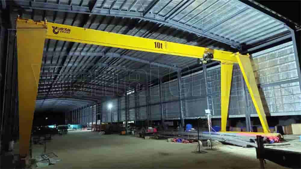
This project involves the installation of a 10T gantry crane, undertaken by China XX Group Co., Ltd. The equipment will be dismantled from its original site and reinstalled at a designated factory. The crane’s main beam is a frame structure, weighing approximately 40T, with a span of 20 meters and a lifting height of 10 meters. This constitutes a large-scale equipment installation project. To ensure construction safety and efficiency, this installation plan has been developed.
II. Preparation Basis
“Code for Construction and Acceptance of Crane Equipment Installation Projects” (GB50278-2010)
“General Code for Construction and Acceptance of Mechanical Equipment Installation Projects” (GB50231-2009)
“Code for Construction and Acceptance of Steel Structures” (GB50205-2001)
Installation drawings and technical documents provided by the equipment manufacturer
On-site measurement data and site conditions
III. Main Equipment Parameters
Parameter items
Numerical
Rated lifting capacity
10T
Span
20m
Overhang
5.2 meters left/6.5 meters right
Lifting height
10m
Lifting speed
8m/min
Running speed
87m/min
IV. Pre-Installation Preparations
(I) Technical Preparations
Family familiarize yourself with the installation drawings and clearly identify the location and installation orientation of the conductive side of the trolley.
Verify the track installation quality:
Level difference between tracks on the same side ≤ 2mm
Level difference between two tracks ≤ 8mm
Difference between track centers ≤ 2mm
Track gauge tolerance ≤ 5mm
(II) Site Preparations
Use a 50T mobile crane as the main crane and dock it at the designated installation site.
Clean the installation area, establish a vehicle access route and work space.
Prepare ground anchors and draw a schematic diagram to calibrate the anchor point locations.
(III) Material Acceptance
Check the parts according to the delivery list, checking specifications and quantities.
Inspect and repair any deformation or damage to major components.
Prepare 12mm guy rope, jacks, wrenches, and other tools.
V. Installation Process
(I) Component Unloading
Unload the traveling crossbeam, outriggers, main beam, and other components in order.
Avoid stacking them tightly. Place the lower crossbeam directly on the designated track location.
(II) Outrigger Installation
Assemble the end beam and outriggers, connecting them according to the numbering and ensuring that the bolt holes align.
Secure the upper ends of the outriggers with 20# channel steel.
Lift the outrigger assembly (approximately 10 tons per unit) onto the track, locking the bottom wheels.
Install the outriggers symmetrically on both sides and secure them with 3′ steel wire ropes.
(III) Main Beam Lifting
Position a 50T truck crane directly in front of the main beam.
After securing the lashings, conduct a test lift. Lift to a height of 100-200mm and hover for 5-10 minutes to check balance and braking.
After optimal adjustment, hoist the components above the outriggers and secure them securely.
(IV) Accessory Installation
Lift the trolley, rain cover, ladder platform, and other components.
Install the electrical system, railings, and other miscellaneous components.
Assemble the control cab, platform, and other welded components.
VI. Quality Assurance Measures
Track installation uses paired inclined irons for adjustment, maintaining levelness within 5mm.
Maintain a 3-5mm gap between the electric hoist wheel and the track.
Bolt hole spacing on the main beam connection surface is measured and adjusted in real time.
Personnel working at height must wear a safety belt.
VII. Safety Assurance Measures
Pre-lifting drills are conducted, with standardized command language.
Standing below the lifting area is strictly prohibited.
Outrigger verticality is corrected using windlasses.
Provision of temporary ladders and guardrails is required.
VIII. Construction Equipment Plan
Machine name
Specifications
Quantity
Truck crane
50T
1 unit
Wire rope
φ15.5mm
Several
Jack
10T
2 unit
Theodolite
J2
1 unit
IX. Workforce Planning
Type of work
Number of people
Responsibilities
Crane Operator
4
Directing lifting operations
Installer
6
Component assembly and fastening
Electrician
2
Electrical system installation and commissioning
Safety Officer
1
On-site safety supervision
X. Trial operation and acceptance
No-load test: Checks the flexibility of the operating mechanism.
Dynamic load test: Tests at 1.1 times the rated load.
Static load test: Tests at 1.25 times the rated load.
Completes handover and acceptance procedures.
Contact our crane specialists
Send us a message and we will get back to you as soon as possible.