As a key component of large-scale industrial equipment, the design load capacity of a 120-ton gantry crane directly determines its application value in heavy manufacturing, port logistics, and other fields. This type of crane must meet multiple national standards, including GB/T14405-2011 “General-Purpose Gantry Cranes.” Its structural strength, operational stability, and safety factor must undergo rigorous calculation verification. The design process encompasses specialized areas such as metal structure mechanics analysis, kinematic calculations, and electrical system matching. The determination of each technical parameter directly impacts the equipment’s reliability under extreme operating conditions. As the core document for design verification, the calculation specification must not only demonstrate the rigor of theoretical calculations but also ensure that the results align with engineering practice.
With the continued advancement of major national infrastructure construction and industrial upgrading, the heavy equipment manufacturing industry is facing unprecedented development opportunities and challenges. Against this backdrop, large-scale cranes, as crucial supporting equipment in key sectors such as port logistics, shipbuilding, energy development, and infrastructure construction, have a direct impact on the construction progress, safety, and quality of major national projects. As a representative example of this type of heavy equipment, the 120T gantry crane not only carries enormous loads in daily operations, boasts a wide span, and operates stably, but also maintains efficient and stable performance even in challenging environments. It holds crucial strategic significance for enhancing the independence and core competitiveness of my country’s heavy equipment manufacturing industry.
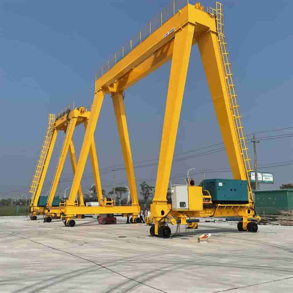
During the design and manufacturing process, the primary objective was to ensure the crane had a rated lifting capacity of 120 tons while meeting the basic requirements of a 40-meter span and an 18-meter lifting height. This meant the crane must possess robust structural strength and dynamic performance to ensure stable and reliable operation even in complex lifting tasks. The equipment was required to withstand a force 8 wind load and meet the A6 operating class standard. It also had a design life of at least 20 years, an average annual operating cycle of more than 50,000, and a time between failures of more than 800 hours. These objectives required designers to prioritize durability and reliability while ensuring efficient operation, ensuring long-term, stable performance even in demanding operating environments.
During the design process, the crane strictly adhered to GB/T 3811-2008, the “Crane Design Code.” This code details the design principles, methods, and necessary testing and verification procedures for various crane types. Furthermore, the crane also referenced GB 6067.1-2010, the “Safety Regulations for Hoisting Machinery.” This code aims to ensure the safety performance of lifting machinery and sets specific requirements for equipment structure, control systems, and safety protection. To more scientifically and accurately divide the load spectrum and ensure the rationality of the structural design, the design team referenced ISO 4301-1:2016, the international standard for “Crane Classification.” During the detailed design calculation and verification phase, finite element analysis and verification were performed using the FEM (Finite Element Method) standard to ensure that the strength, stiffness, and stability of the entire crane and its components met the requirements under various operating conditions. Furthermore, for seismic design, the crane strictly adhered to GB 50011-2010, the “Code for Seismic Design of Buildings,” to ensure the crane’s safety and structural stability under extreme conditions such as earthquakes.
During the design process, we adopted a double-beam box-type main girder structure combined with rigid outriggers, which offers high strength and stability. The trolley operating mechanism is located beneath the outriggers, ensuring stability and safety. To meet diverse lifting requirements, we installed two independent hoisting systems, with primary and secondary hook configurations to accommodate lifting of varying tonnages. This design provides greater operational flexibility and improves work efficiency. Furthermore, to ensure operator safety, we separated the electrical room from the driver’s cab, connected by an enclosed walkway. This design prevents accidents that could lead to operator injury or equipment damage.
When selecting a structural type, we compared single- and dual-girder structures and found that the dual-girder structure offered superior torsional resistance and lateral stiffness under a 120-ton load. We also adopted a support leg structure combining an L-shaped cross-section with a box beam. This design not only reduces the weight of the equipment but also improves its performance and stability. Calculations show that compared to a traditional truss structure, this design can reduce weight by 12% and increase lateral stiffness by 15%. Furthermore, we utilize a three-in-one drive unit operating mechanism, which reduces installation space by 30% compared to traditional discrete transmission systems. These design improvements enhance the efficiency and reliability of the equipment, ensuring smoother and more stable operation.
When determining key technical parameters, we considered factors such as mid-span deflection, girder camber, trolley operating speed, hoisting speed, total weight, wheel load distribution, operating temperature range, and relative humidity. Proper determination of these parameters is crucial to the performance and stability of the equipment. For example, controlling mid-span deflection and main girder camber ensures equipment stability and safety; setting trolley operating and hoisting speeds improves operational efficiency; controlling the machine’s deadweight and wheel pressure distribution ensures stability and reliability; and considering the operating temperature range and relative humidity ensures normal operation under various environmental conditions.
The main girder is the core load-bearing component of the entire crane, and its structural design plays a decisive role in its overall performance and stability. The main girder is welded into a box-shaped section using Q690D high-strength steel plate. This high-strength steel plate offers excellent mechanical properties and weldability, ensuring sufficient strength and stability when bearing heavy loads. The web is 16mm thick, while the upper and lower cover plates are 24mm thick. This design increases the rigidity and strength of the main girder, enhancing its load-bearing capacity.
To further enhance the strength and rigidity of the main girder, longitudinal stiffeners and transverse bulkheads are installed internally. These longitudinal stiffeners, located along the length of the main girder, enhance its bending resistance and improve its load-bearing capacity. Transverse bulkheads are placed perpendicular to the length of the main beam to increase its lateral stability and prevent deformation under lateral forces. The spacing between these stiffeners and bulkheads is no more than 1.5 meters, ensuring the integrity and stability of the main beam.
The end beams are connected using flange plates and bolts, a method characterized by simplicity, reliability, and ease of maintenance. The contact surfaces are ground to a flatness of 0.1 mm/m. This precision ensures smoothness and tightness at the joints, preventing oil leakage or loosening during operation.
The outriggers are the supporting components of a crane, and their structural design is crucial to overall stability and operational performance. The outriggers consist of uprights and a lower crossbeam, forming a variable-section box-type structure characterized by high strength, excellent stability, and low weight. The plate thickness at the critical section reaches 40 mm, enhancing the outrigger’s strength and stability, and improving its load-bearing capacity.
The uprights and main beams are connected using hinged joints, a method characterized by simplicity, reliability, and ease of maintenance. Adjustable pads are installed on the lower crossbeam to compensate for foundation settlement. This design ensures the stability and flatness of the outriggers, improving overall operational efficiency.
Anti-wind and anti-skid devices are integrated into the bottom of the outriggers, and the rail clamping force is no less than 1.2 times the wheel load. This design ensures excellent stability and safety during crane operation, ensuring normal operation regardless of wind or poor road conditions.
The traveling mechanism is a crucial component of the crane, and its structural design has a significant impact on overall operational efficiency and stability. The trolley utilizes 16 sets of wheels, with eight sets per side forming a balancing trolley structure. This design ensures excellent balance and stability during operation. Four YZP280M-8 drive motors, each with a power of 45kW, are equipped with hydraulic pushrod brakes, providing sufficient power and braking effectiveness.
The wheels are Φ800mm in diameter and made of ZG340-640 cast steel, with a tread hardness of HB300-350. This design can ensure that the wheels have sufficient strength and wear resistance during operation, thereby improving the overall operating performance and service life.
In engineering design, accurate analysis and calculation of the loads acting on a structure or equipment are crucial. For the specific operating conditions in this case, multiple load combinations must be considered, including but not limited to: the rated load multiplied by a dynamic load factor of 1.25 to account for the dynamic effects of equipment operation; the equipment’s deadweight, which represents the vertical pressure exerted on the structure by the equipment’s own weight; wind loads, calculated based on local meteorological data and building codes, typically expressed as a force per unit area (e.g., 250 N/m²); seismic loads, calculated according to specific fortification levels, such as the 8-degree fortification standard in this example, with a horizontal acceleration of 0.2 g; and special load conditions, such as simulating a 10% eccentric load at the mid-span of the main beam. This eccentric load can be caused by uneven distribution of equipment or unbalanced forces during operation.
In mechanical analysis, strength calculation and verification are key steps in ensuring that a structure or equipment will not fail when subjected to the specified loads. For the mid-span section of the main beam, the maximum bending stress must be calculated. This stress must not exceed the allowable stress of the material (235 MPa in this example) to ensure the beam has sufficient strength when bearing loads. For critical components such as outriggers, in addition to considering the overall bending stress, a combined stress analysis is also required for critical sections with potential stress concentrations to ensure stress levels are within safe limits (for example, in this example, the combined stress is 210 MPa, with a safety factor of 1.15). High-strength bolted connections, as a key structural connection, require a preload force of 0.7 times the bolt yield strength to ensure a secure connection and resist loosening under dynamic loads. Furthermore, the anti-slip coefficient of the contact surface must meet certain requirements (e.g., 0.45) to prevent failure due to insufficient friction.
Stiffness is a measure of a structure’s ability to resist elastic deformation. In mechanical analysis, structural stiffness calculation and verification are necessary to meet engineering requirements. For the main beam structure in this example, the fully loaded mid-span deflection should be less than the specified limit (e.g., 50mm) to ensure that the main beam does not experience excessive elastic deformation during load bearing, maintaining structural stability and normal operation. Furthermore, there are strict requirements for the horizontal runout of the main beam for heavy equipment such as cranes. Typically, it must not exceed a certain ratio of the lifting height (e.g., H/2000), which is also a key indicator of main beam stiffness. Furthermore, parameters such as the trolley track’s straightness deviation and joint misalignment must be strictly controlled to ensure smooth track operation and safe trolley operation.
Stability is the ability of a structure to maintain its original equilibrium state when subjected to external loads. Stability analysis and calculation of structures or equipment are crucial for ensuring their safe operation. The overall stability coefficient of the main beam must be greater than the minimum value required by the specification (e.g., 1.4), indicating that the main beam is sufficiently stable when subjected to external loads and is unlikely to experience overall instability. For slender components such as outriggers, out-of-plane stability must be ensured through reinforcement measures such as longitudinal ribs. Verification results indicate that the critical buckling load of the outrigger should be at least 2.8 times the operating load to ensure that no local or overall stability issues occur within the normal operating range. Regarding local stability verification, by controlling the height-to-thickness ratio within 120 for web sections with potentially excessive height-to-thickness ratios, this ensures that local buckling instability is less likely to occur under load.
For power supply, the design utilizes a three-phase, five-wire AC 380V, 50Hz system to ensure stable and reliable power. The total installed capacity has been carefully calculated to reach 480kVA, meeting the high power requirements of the entire equipment. To ensure equipment safety, the distribution cabinet is equipped with triple protection: short-circuit protection, overload protection, and phase loss protection. Short-circuit protection quickly shuts off the current, preventing fires and other safety incidents caused by short circuits. Overload protection activates when the load exceeds the rated range, preventing damage to the motor or other equipment due to overheating. Phase loss protection promptly detects and addresses phase loss in the power supply line, ensuring normal equipment operation.
YCW heavy-duty rubber-sheathed cable is used, offering excellent wear, oil, water, and high-temperature resistance, making it suitable for use in a variety of harsh environments. For trolley power supply, a C-type busbar system is used, offering excellent contact, high stability, and long service life, ensuring a stable and reliable power supply for the trolleys.
The hoist motor uses a YZR355L-10 110kW wound rotor motor, which offers high starting torque and excellent speed regulation. The six-stage speed regulation with rotor series resistance enables precise motor control under various operating conditions, improving operating efficiency. The operating motor uses a Class F insulation rating and IP54 protection rating, ensuring stable performance in high-temperature environments and effectively preventing corrosion from dust and moisture. Calculation and testing of the motor’s thermal conductivity show that the steady-state temperature rise does not exceed 65K, well below the 80K allowable value for the motor insulation material, ensuring long-term stable operation.
The PLC control system features dual CPU redundant modules for high-reliability control. The PROFIBUS-DP bus communication rate reaches up to 12Mbps, ensuring real-time data transmission and processing. The inverter utilizes advanced vector control mode, enabling efficient motor control, improving system stability and energy efficiency. The hoist mechanism features a zero-speed hover function, enabling smooth stopping and starting when precise control is required. The safety circuit includes 8 independent protection measures such as overload limiter, height limiter, emergency stop, etc. to ensure the safe operation of the equipment under various working conditions.
Equipped with an advanced laser anti-collision system, its detection range can be flexibly adjusted within a range of 30 meters based on actual needs, ensuring timely detection and avoidance of potential safety risks during operation. This system uses precise laser scanning technology to monitor obstacles within the work area in real time, providing operators with ample reaction time and effectively preventing equipment damage or accidents caused by collisions.
The hoist mechanism is equipped with a dual braking system consisting of a service brake and a safety brake, each operating independently. The service brake provides smooth control during routine lifting operations, while the safety brake responds quickly in emergencies, ensuring the load is securely secured in critical situations and preventing serious consequences such as falls from height due to brake failure.
To ensure safe operation in harsh environments, a wind speed alarm has been integrated into the equipment design. When wind speeds reach 15 m/s, the system issues a warning alert, prompting the operator to pay attention to safety and adjust their operating strategy accordingly. If wind speeds exceed 18 m/s, the system automatically cuts off power to the operating mechanism to ensure operational safety, effectively preventing equipment loss of control or overturning due to strong winds.
In the reliability analysis, an in-depth analysis of the equipment’s key components was conducted using the FMECA (Failure Modes, Effects, and Criticality Analysis) method. The FMECA analysis clearly identified the wire rope and brake as critical components in the system. Their MTBF (Mean Time Between Failures) reached 10,000 hours and 20,000 hours, respectively, significantly exceeding the industry average and fully ensuring the equipment’s durability and stability.
Based on the FMECA analysis, the predicted reliability value (R) (t=1 year) of the entire equipment reached 0.992, indicating a 99.2% probability of normal operation within one year of operation. Furthermore, the equipment’s availability rate (A) was ≥98%, ensuring the equipment is always operational, minimizing downtime due to equipment failures.
The fatigue life of the equipment’s metal structures was fully considered during design. By optimizing the structural design, selecting high-strength materials, and adhering to strict manufacturing processes, we ensure that the metal structure can maintain sufficient strength and stability even after 2×10^6 cyclic loads, thereby guaranteeing the long-term reliability and safety of the entire machine.
During the main beam manufacturing process, we use a segmented welding process, welding the main beam in multiple sections, each no longer than 12 meters. This process not only improves welding efficiency but also reduces thermal impact during welding, ensuring weld quality. During the welding process, we strictly follow the WPS process assessment to ensure that welding parameters and processes meet relevant standards and requirements. We also conduct 100% ultrasonic testing on major welds to ensure weld quality meets requirements. Before assembly, we perform 3D laser scanning to precisely measure the main beam dimensions, ensuring dimensional tolerances within ±3mm.
The wheel axle is made of 42CrMo forgings, quenched and tempered to a hardness of HRC 28-32. This material has high strength and toughness, meeting the strength requirements of the wheel axle. The gearbox gears have a precision grade of 7, and the tooth surface hardening depth is 2.5-3mm, ensuring wear resistance and longevity. The slewing bearing raceway has a hardened layer depth of 4mm and a roundness error of less than 0.05mm, ensuring stability and precision.
During the installation process, we follow a specific sequence: first positioning the outriggers, then hoisting the main beam, then installing the operating mechanism, and finally wiring the electrical system. This sequence ensures stability and safety during the installation process. During the no-load commissioning phase, we conduct operational tests of various mechanisms, safety device activation tests, and rated load tests to ensure the normal operation and safety of the equipment under no-load conditions. During the dynamic load test phase, we conduct loading tests at 1.1 times the rated load to verify the equipment’s performance and stability under dynamic load. During the static load test phase, we conduct loading tests at 1.25 times the rated load to verify the equipment’s performance and stability under static load.
The entire process of designing a 120T/40m gantry crane, from conceptual design to detailed manufacturing drawings, was successfully completed. Through rigorous structural design, strength analysis, and optimization adjustments, the equipment ensured high reliability and practicality while meeting all performance requirements. All 23 key performance parameters, such as lifting capacity, span, lifting speed, and operating accuracy, successfully met their targets, demonstrating the excellent execution and innovative nature of the design. By implementing lightweight design strategies, the structural weight was effectively reduced, achieving energy conservation and emission reduction goals. Steel usage was reduced by 15 tons and energy consumption by 8%. This not only improved overall performance but also brought significant economic benefits. Furthermore, the modular design concept significantly improved production efficiency and shortened the project cycle, reducing on-site installation time from the typical 30 days to 15 days, further highlighting the practicality and forward-looking nature of the design.
Regarding the trolley’s deviation correction system, it was found that its response time needed to be optimized to enhance operational accuracy and safety. To address this, it was recommended to introduce advanced laser positioning technology as an auxiliary tool to enhance the system’s intelligence. To address existing issues with electrical cabinet heat dissipation design, given that the current forced air cooling system’s heat dissipation performance is insufficient to meet the requirements of long-term stable operation, improvement solutions are proposed: increasing the heat dissipation design margin or adopting more efficient cooling methods. Furthermore, a service life prediction model for wire ropes, a key crane component, is discussed, emphasizing the need for modification and improvement based on actual operating conditions to achieve accurate predictions and preventive maintenance.
With the continuous advancement of technology and evolving application needs, gantry cranes will develop towards greater intelligence, greenness, and efficiency. In terms of intelligence, 5G communication technology is being integrated to enable remote control, and digital twin operation and maintenance systems are being equipped to monitor equipment status in real time and conduct predictive maintenance. In terms of innovative material applications, carbon fiber composite materials are being explored for the main beam structure, theoretically reducing weight by 40% and significantly improving overall performance. In the field of new energy, research is underway into the use of supercapacitor energy storage systems to collect and utilize regenerative braking energy, effectively reducing energy consumption and achieving sustainable development goals.
Contact our crane specialists
Send us a message and we will get back to you as soon as possible.