The installation of large industrial equipment requires systematic and standardized implementation plans as guidance. The 16-ton gantry crane, as heavy lifting equipment, involves multiple professional fields such as structural assembly, electrical debugging, and safety configuration during its installation process. A scientific and reasonable installation plan is the fundamental guarantee for ensuring stable equipment performance and operational safety. This plan forms a complete closed loop from preliminary preparation to final acceptance, with each link requiring strict execution of technical specifications. The installation team must possess professional qualifications and extensive experience, and proceed orderly according to the established process based on a full understanding of equipment characteristics and site conditions.
The installation site survey is the primary step to ensure the smooth installation of the gantry crane. Survey personnel need to conduct detailed measurements of the installation site, including key parameters such as ground flatness, load-bearing capacity, and spatial dimensions. Ground flatness is a crucial factor affecting the gantry crane installation and must be accurately measured using professional equipment to ensure it meets the installation requirements. Load-bearing capacity is a key factor related to the safe operation of the gantry crane. The ground bearing capacity must be evaluated to ensure the ground can withstand the weight of the gantry crane and the load during operation. Spatial dimensions significantly impact the operating range and efficiency of the gantry crane. The site space must be fully assessed to ensure sufficient operating space for the gantry crane. Based on the survey data, an installation layout plan should be drawn, clearly defining the equipment positioning points, travel rail path, and auxiliary facility locations. The equipment positioning points should consider the operating range of the gantry crane and the distribution of surrounding obstacles to ensure a reasonable installation location. The travel rail path should consider the site space and equipment positioning points to ensure stable and firm rail installation. The locations of auxiliary facilities should consider equipment operation and personnel operational needs to ensure they are complete and practical.
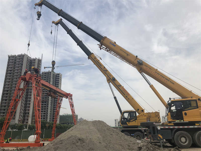
Table: Installation Site Survey Data Sheet
| Survey Item | Measurement Method | Key Parameter Requirements | Evaluation Standard | Tools/Equipment | Relevant Certificates/Qualifications |
|---|---|---|---|---|---|
| Ground Flatness | Laser Level Measurement | Deviation ≤3mm/㎡ | GB/T 50344-2019 Code for Deformation Measurement of Building Structures | Laser Level, Spirit Level | Surveyor Qualification Certificate |
| Ground Bearing Capacity | Static Load Test / Ground Penetrating Radar Scan | ≥15t/㎡ (Including Safety Factor) | GB 50007-2011 Code for Design of Building Foundation | Hydraulic Jack, Pressure Sensor | Geotechnical Engineer Practicing Qualification |
| Spatial Dimensions | Total Station 3D Scanning | Span Error ≤10mm, Clearance ≥1.5m | GB/T 3811-2008 Design Rules for Cranes | Total Station, Steel Tape Measure | Special Equipment Inspector Certificate |
| Rail Path | Theodolite Positioning Measurement | Straightness ≤2mm/m, Gauge ±3mm | JB/T 6392-2010 Specification for Installation of Crane Tracks | Theodolite, Track Gauge | Hoisting Machinery Installation and Maintenance Certificate |
| Auxiliary Facility Layout | BIM Simulation and Site Staking Out | Complies with GB 50034-2013 Lighting Standard, Equipment Operation Space ≥0.8m Safety Distance | Total Station, BIM Software | Electromechanical Installation Engineer Qualification |
Table: Installation Team Organization and Tool Configuration Table
| Position/Role | Responsibility Scope | Qualification Requirements | Special Tools | Safety Protection Equipment | Typical Work Tasks |
|---|---|---|---|---|---|
| Project Manager | Overall Coordination and HSE Management | Grade 1 Constructor (Electromechanical Engineering) | Project Management Software | Safety Inspection Recorder | Construction Plan Approval |
| Mechanical Engineer | Structural Installation Technical Guidance | Engineer Title (Mechanical Design) | Hydraulic Torque Wrench (3000Nm) | Fall Arrest Safety Harness | Main Girder对接精度控制 (Docking Accuracy Control) |
| Electrical Engineer | Control System Debugging | Registered Electrical Engineer | Multimeter (Fluke 87V) | Insulating Gloves | Frequency Converter Parameter Setting |
| Rigger | Lifting Operation | Q2 Gantry/Bridge Crane Operation Certificate | 50-ton Truck Crane (SAC5000) | Safety Helmet (3M H-700) | Leg Assembly and Hoisting |
| Welder | Rail Welding and Structural Reinforcement | Pressure Vessel Welder Certificate (GTAW-6G) | Inverter Welding Machine (Lincoln V350) | Welding Mask (Auto-Darkening) | Rail Joint Welding |
| Surveyor | Installation Accuracy Inspection | Engineering Surveyor (Intermediate) | Total Station (Leica TS16) | Reflective Vest | Rail Straightness Detection |
The professional installation team consists of project managers, mechanical engineers, electrical engineers, riggers, welders, and other professionals. The project manager is responsible for overall coordination and safety management, the mechanical engineer leads the technical guidance for structural installation, and the electrical engineer undertakes system debugging tasks. Personnel of various trades must hold corresponding operational qualification certificates, including but not limited to nationally recognized special equipment operator certificates, electrician certificates, etc. Before starting the installation, safety technical briefings must be conducted for all personnel involved in the installation to clarify their respective tasks and responsibilities, and emergency plan drills should be conducted to ensure a rapid response in case of emergencies.
Before starting the installation, it is essential to ensure that all necessary tools and materials are ready. Special equipment such as 50-ton truck cranes, hydraulic torque wrenches, laser levels, etc., should undergo integrity checks to ensure they function properly during the installation process. Standard parts such as high-strength connecting bolts, rail clamps, cable trays, etc., should also be prepared, and their quality must meet the requirements. All tools and materials must be strictly inspected before entering the site to ensure they meet the installation needs. Additionally, sufficient spare parts and tools should be prepared for contingencies.
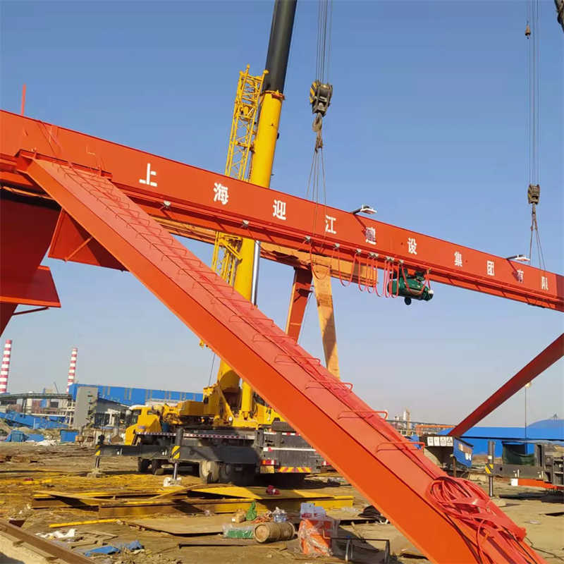
The hoisting and connection of the main girder is a critical part of the entire gantry crane installation process. To ensure the stability and safety of the main girder during hoisting, a segmented installation process is adopted, using a spreader beam配合 (coordinated with) a four-point hoisting method. This method maintains the main girder level during hoisting, avoiding deformation or damage caused by uneven force or improper hoisting. At the docking points of the main girder, Grade 10.9 high-strength bolts are used for connection. To ensure a firm and reliable connection, the pre-tightening force is applied in three stages up to the design torque value. After each application of pre-tightening force, a torque check is performed to ensure the bolt connection torque meets the design requirements. Simultaneously, the flatness of the main girder is strictly controlled, requiring the deviation to be within L/1000. If it exceeds this range, adjustments are needed to ensure the flatness and stability of the main girder. For the docking welds of the main girder, 100% ultrasonic testing is performed. This ensures the quality and reliability of the welds, further enhancing the safety performance of the gantry crane.
The installation and fixation of the legs are crucial for the overall stability of the gantry crane. During the installation process, the verticality deviation of the legs is strictly controlled, requiring it not to exceed H/2000. To achieve this goal, a theodolite is used for bidirectional verticality monitoring. During the leg installation process, the secondary grouting of anchor bolts is an important task. C35 micro-expansive concrete is used for grouting to ensure a tight combination between the anchor bolts and the foundation embedded parts. During the grouting process, the concrete mix ratio and pouring quality need to be strictly controlled to ensure sufficient strength and stability. During the curing period, no load should be applied to the anchor bolts to ensure they fully cure. To increase the strength and stability of the connection node between the legs and the main girder, shear keys are installed. Simultaneously, ensure that the contact surface gap meets the requirements, checked with a 0.03mm feeler gauge which should not pass through.
The laying and adjustment of the rails significantly impact the performance and safety of the gantry crane. Before rail installation, the position deviation of the foundation embedded parts must be inspected. If the position deviation is too large, timely adjustment is needed to ensure the accuracy and stability of the rail installation. When laying the rails, the misalignment amount at the rail joints must be strictly controlled, requiring it not to be greater than 1mm. Simultaneously, elastic shims are used to level the rails, ensuring their flatness and stability. To meet usage requirements, the gauge tolerance needs to be controlled within ±5mm. If the gauge exceeds this range, adjustment is required. To prevent derailment or creeping of the gantry crane during operation, buffer stops are installed at the rail ends. Simultaneously, ensure a 50mm gap is maintained between the end stop and the buffer contact surface. This can absorb impact force to a certain extent and reduce the risk of damage.
In the installation and debugging process of the electrical system, the installation accuracy of the power distribution cabinet is a key link. To ensure its normal operation, installation must strictly comply with specifications, with verticality deviation less than 1.5mm/m. This requirement aims to avoid electrical contact issues or operational malfunctions caused by minor deformations. The design and installation of cable trays also require precision; their bending radius must be greater than 10 times the cable diameter, aiming to ensure smooth passage of cables within the tray and reduce the risk of cable damage caused by friction.
For the laying of power cables and control cables, the principle of layered arrangement must be followed to ensure various cables do not interfere with each other, thereby improving system stability and safety. The trolley travel mechanism adopts a conductor rail power supply system. This design not only improves power supply efficiency but also reduces operational risks. To ensure the reliability and stability of electrical connection points, all connection points should have anti-loosening measures applied, such as lock washers. The test value of the grounding resistance is crucial and must be controlled to not greater than 4Ω to avoid equipment operational instability or safety hazards caused by excessive resistance.
The frequency converter is the core component in modern electrical drive systems, and its parameter settings directly affect the motor’s working efficiency and stability. During the debugging process, strictly follow the motor nameplate data to set the frequency converter parameters, ensuring that parameters such as current, voltage, and speed are within reasonable ranges under various operating conditions. The trial operation time of each mechanism under no-load conditions should not be less than 2 hours. This is to fully test the smoothness and reliability of its start-up, operation, and stopping processes.
During the testing phase, conduct tests on the motor at various levels such as jog, slow speed, and full speed to confirm the response speed and load capacity under different working conditions. Pay special attention to the motor’s three-phase current unbalance rate, strictly controlling it within 5%, to prevent equipment overheating, low efficiency, etc., caused by excessive or insufficient current. As an important component of the electrical control system, the repeat accuracy of the limit switch’s actuation position directly affects the equipment’s positioning accuracy and operating efficiency. During the debugging process, ensure the repeat accuracy of the limit switch’s actuation position reaches ±3mm to meet the requirements for high-precision equipment operation.
The lifting height limiter is an important guarantee for the safe operation of hoisting machinery and must undergo strict simulated trigger tests. During testing, by simulating a scenario of 110% of the rated height, verify whether the limiter can actuate accurately and cut off the lifting power source, preventing equipment failure or safety accidents caused by overload or misoperation. Simultaneously, the response time of the emergency stop button is strictly controlled within 0.5 seconds to ensure the power can be cut off quickly in emergencies, safeguarding personnel and equipment safety.
The calibration of the wind speed alarm device is equally important. It must accurately trigger a warning signal at a wind speed of 15m/s, enabling timely countermeasures to prevent operational risks caused by windy weather. As an important warning means for on-site operations, the audible and visual alarm system’s coverage must effectively cover the entire work area, ensuring alarm information can be received promptly in any corner, further enhancing the safety of the work site.
The installation angle of the travel limit switch dog needs to be perpendicular to the direction of travel to ensure the limit switch can trigger accurately. To ensure the reliability of the limit switch, a 10% margin needs to be reserved for the buffer distance. Furthermore, the dual limit system sets up secondary protection. When the first stage limit is triggered, a 200mm safety distance needs to be retained to avoid excessive wear or damage to the limit switch. Simultaneously, the limit switch contact pressure needs to be adjusted to the range of 1.5-2.5N to ensure the limit switch can function properly.
The installation centerline of the polyurethane buffer needs to coincide with the track center, and the compression should not exceed 50% of the total height, to ensure the buffer’s performance and stability. The hydraulic buffer needs to have an oil fill level up to the calibration mark, and the piston rod movement should be free of sticking, to ensure the normal operation of the buffer. The buffer distance needs to be checked according to 120% of the rated operating speed, to ensure the buffer’s effectiveness and safety.
The floodlight’s irradiation angle needs to cover the spreader work area, with an illuminance not less than 50lux, to ensure sufficient lighting in the work area. The audible and visual alarm needs to be installed at a height of more than 3m above the ground, with a warning sound level reaching 85 decibels, to alert surrounding personnel to safety. The control cabin needs to be equipped with an emergency lighting system, with a continuous power supply time greater than 30 minutes, to ensure normal operation in case of emergencies.
During the installation process, the GB/T14405-2011 standard must be strictly followed, as it is the basic requirement for ensuring structural installation quality. Simultaneously, the installation of the electrical system must comply with GB5226.2 requirements, ensuring the normal operation and safety of electrical equipment. To ensure timely discovery and resolution of quality issues during installation, we adopt a phased approach for hidden works acceptance, ensuring every step meets quality standards. For critical processes, we implement a supervision station system. Through third-party supervision, the installation process is ensured to be fair, transparent, and compliant with relevant regulations and standards. To ensure the quality of welds in metal structures, we conduct 20% random radiographic inspection. If unqualified areas are found in the test results, we will double the re-inspection until the problem is thoroughly resolved.
Technical documents are an important basis for acceptance, including 12 items such as product certificates, material certificates, and installation self-inspection records. These documents need to be prepared in advance and ensured to be authentic and complete. To verify the load-bearing capacity of the equipment, we need to prepare a load test plan, specifying the procedures for 125% static load and 110% dynamic load tests. This ensures the equipment has sufficient load-bearing capacity during normal operation, avoiding safety accidents caused by overload. Before installing special equipment, a notification letter needs to be submitted to the local regulatory authority for filing. This is not only a legal requirement but also an important step to ensure the installation is legal and compliant.
The acceptance team consists of representatives from the construction unit, the supervision unit, and the installation unit. To ensure the fairness and accuracy of the acceptance results, the load test duration should not be less than 10 minutes. If any problems occur with the equipment during the test, we need to take timely measures for handling. The standard for qualified structural integrity is the absence of permanent deformation. To ensure the reliability of the acceptance results, the acceptance records adopt a dual-person verification system. Furthermore, we require that image data be kept for a period not less than the equipment’s service life. These measures help us review the acceptance results at any time during the equipment’s service life, ensuring the equipment is always in good operating condition.
Daily maintenance work is the foundation for ensuring normal equipment operation. First, conduct careful inspections of key components such as wire ropes. Once wear exceeding the specified standard is found, especially if the number of broken wires exceeds 10% of the total wires, replacement should be arranged immediately to eliminate potential safety hazards. Weekly lubrication of all transmission components is required, ensuring bearing housings are filled with fresh, high-quality lithium-based grease to reduce friction and extend service life. Monthly, conduct a comprehensive tidying up of the electrical control system, especially thoroughly cleaning dust inside the electrical cabinet to maintain cleanliness and prevent circuit failures. Also, meticulously check for contact burning on contactor contacts, and repair or replace them promptly if necessary.
Semi-annually, conduct professional inspections of the tracks for settlement. Once uneven settlement is found, adjust the shims immediately to ensure smooth equipment operation. Annual overhaul is a crucial maintenance activity, including but not limited to replacing the lubricating oil in the reducer, disassembling, inspecting, and maintaining the brake, ensuring various safety performances meet standards. Furthermore, for the metal structure part, a comprehensive and detailed inspection should be conducted every three years to observe the development of fatigue cracks, assess the durability of structural members, and take corresponding repair or replacement measures based on the evaluation results.
Establish a comprehensive digital equipment file system, detailing and entering information such as the time of each maintenance service, specific work content, replaced parts information, and other important repair histories. For key components, establish a life prediction model based on their service life and wear patterns, issuing early warnings three months in advance to prevent sudden failures. Simultaneously, the retention period for all maintenance and servicing records shall not be less than three years after equipment scrapping. This not only facilitates traceability and querying but also helps summarize equipment operation patterns and improve equipment management efficiency.
Contact our crane specialists
Send us a message and we will get back to you as soon as possible.