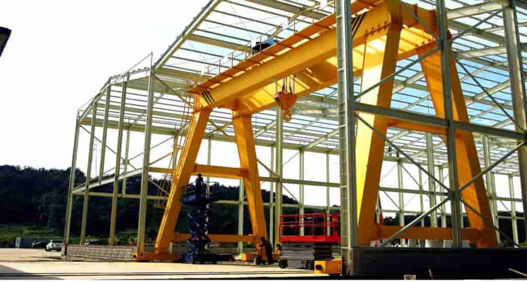
As a core piece of equipment in the field of industrial material handling, the 16t Double Girder Gantry Crane plays a key role in scenarios such as port loading/unloading, warehouse logistics, and heavy-duty manufacturing, thanks to its exceptional load-bearing capacity and structural stability. The equipment adopts a modular double girder box-type structure design, equipped with an advanced variable frequency speed control system and multiple safety protection devices. While ensuring the 16-ton rated lifting capacity, it achieves precise and smooth load positioning. Its large-span gantry structure adapts to outdoor working environments, and the rail traveling mechanism supports long-distance material transfer needs. The intelligent control system meets the dual standards of efficiency and safety required by modern industrial production.
The 16t Double Girder Gantry Crane is a heavy-duty material handling equipment designed for large-scale factories, warehouses, docks, and other sites, featuring large spans and high lifting capabilities. It utilizes a double main girder box-type structure design, making the entire machine more robust with excellent load-bearing capacity and wind resistance. This model is equipped with a double-rail trolley traveling mechanism, ensuring smoother and more reliable crane operation. The rated lifting capacity is 16 tons, with a span range of 18-35 meters and a lifting height of 6-30 meters, suitable for loading and unloading operations at open storage yards, freight yards, power stations, and other locations. The gantry structure consists of a rigid leg and a flexible leg, effectively adapting to rail installation errors and ensuring operational stability.
Primarily applied in port container yards, steel plant plate transfer, wind power equipment assembly yards, and other scenarios. Suitable for ambient temperatures of -20°C to +40°C, relative humidity ≤95% (at 25°C), and altitudes below 1000 meters in non-explosive atmospheres. Use is prohibited in flammable, explosive, strongly corrosive environments, and in winds exceeding Force 6.
| Item | Parameter Indicator |
|---|---|
| Rated Load | 16t (Main Hook) + 5t (Auxiliary Hook) |
| Duty Class | A5 (GB/T3811 Standard) |
| Lifting Speed | Main Hook 3.2 m/min (full load) – 8 m/min (no load) |
| Crane Travel Speed | 20-30 m/min (VF Speed adjustment) |
| Trolley Travel Speed | 3-10 m/min (Stepless Speed Variation) |
| Rail Spec | QU70 / QU80 |
Table: Main Technical Parameters of the Crane
| Parameter Category | Specific Parameter | Indicator/Requirement | Standard/Specification | Remarks |
|---|---|---|---|---|
| Rated Load | Main Hook | 16t | GB/T3811 | — |
| Auxiliary Hook | 5t | GB/T3811 | — | |
| Duty Class | — | A5 | GB/T3811 | — |
| Speed Parameters | Main Hook Lift (Full/No Load) | 3.2 m/min / 8 m/min | — | VF Control |
| Crane Travel | 20-30 m/min | — | VF Speed Control | |
| Trolley Travel | 3-10 m/min | — | Stepless Speed Variation | |
| Rail Requirements | Model | QU70/QU80 | — | — |
| Installation Accuracy (Gauge Deviation) | ≤±5mm | — | Foundation Bearing Capacity ≥150 kN/m² | |
| Stiffness Requirements | Static Stiffness | ≤S/1000 | FEM 1.001 | S is Span |
| Dynamic Stiffness | ≤S/800 | FEM 1.001 | — | |
| Braking Performance | Lifting Mechanism Brake Slip | ≤0.2% Rated Load | — | — |
| Noise Level | — | ≤85 dB(A) | GB/T3768 | Measured 1m from source |
| Ground Resistance | — | ≤4 Ω | — | Rail Grounding |
Table: Crane Working Environment and Installation Requirements
| Environmental Condition Category | Inspection Item | Technical Indicator | Measurement Method/Tool | Related System |
|---|---|---|---|---|
| Rail Installation | Gauge Deviation | ≤±5mm | Total Station / Steel Tape | Crane Travel System |
| Rail Level Difference | ≤3mm/10m | Level Gauge | — | |
| Joint Gap | ≤2mm | Feeler Gauge | — | |
| Electrical System | Power Supply Voltage Fluctuation | ±10% Rated Voltage | Power Quality Analyzer | Main Control System |
| Ground Resistance | ≤4 Ω | Ground Resistance Tester | Safety Protection System | |
| Foundation Bearing | Ground Pressure | ≥150 kN/m² | Foundation Bearing Capacity Tester | Steel Structure Support System |
| Environmental Adaptability | Operating Temperature | -20°C ~ +40°C | — | Hydraulic / Lubrication System |
| Max. Relative Humidity | ≤95% (at 25°C) | Temp & Humidity Logger | Electrical Component Protection | |
| Safety Protection | Insulation Resistance | ≥1 MΩ (500V Megohmmeter) | Megohmmeter | Electrical System |
| Wind Speed Limit | ≤20 m/s (Operating State) | Anemometer | Wind Resistance & Anti-Slip Devices | |
| Maintenance Cycle | Wire Rope Inspection | Visual check per shift + detailed monthly inspection | Magnetic Particle Detector | Lifting Mechanism |
| Lubrication Point Maintenance | Replenish lubricant every 100 operating hours | High-Pressure Grease Gun | All Moving Parts |
Engineering design strictly follows FEM 1.001 standards for structural strength calculations, ensuring the equipment meets requirements under various working conditions. Among these, static stiffness requirement is ≤S/1000, and dynamic stiffness requirement is ≤S/800. For the lifting mechanism, braking slip is required to be ≤0.2% of the rated load; for the traveling mechanisms, the braking distance is required to be ≤1/15 of the rated speed. The overall noise level is required to be ≤85 dB(A), complying with the GB/T3768 testing standard.
During equipment use, certain power supply requirements, rail installation accuracy, foundation bearing capacity, and rail grounding resistance must be met. Specifically, the power supply requires a three-phase AC 380V ±10%, 50Hz system. Rail installation accuracy must satisfy: rail gauge deviation ≤±5mm, rail level difference ≤3mm/10m, joint gap ≤2mm. Foundation bearing capacity should be no less than 150 kN/m², and rail grounding resistance should be ≤4Ω.
The complete machine consists of four major parts: metal structure, lifting mechanism, traveling mechanisms, and electrical system. The gantry uses a double girder design with off-track box girders, which increases structural stability and strength while reducing dead weight and material consumption. Main girders and legs are connected via high-strength bolts, a method facilitating installation and maintenance while ensuring structural reliability and stability. The trolley frame is a welded steel plate structure equipped with anti-tipping safety hooks, effectively preventing the trolley from tipping during operation. The operator’s cab complies with GB/T20303 standard, features secondary shock absorption, effectively reducing vibration impact on the operator, improving comfort and safety.
The lifting mechanism is one of the core components of the crane, including the electric motor, coupling, brake, reducer, drum assembly, and hook block. The motor provides power, which is transmitted to the drum assembly after speed reduction by the reducer, causing the drum to rotate and thereby winding or unwinding the wire rope. The crane (gantry) travel mechanism is a crucial component, utilizing four-corner independent drive, ensuring stability and travel efficiency. It is also equipped with buffers, limit switches, and rail sweeps for operational safety. Safety devices also include load limiters, height limiters, anemometers, and emergency power-off switches, effectively ensuring equipment operational safety and user life safety. Electrical control employs a PLC + frequency inverter control system, enabling automated control and energy savings. This system also features CAN bus communication for easy coordination between multiple devices.
Power is transmitted from the motor to the reducer, driving the drum rotation via gear transmission to wind/unwind the wire rope. Crane travel uses bogie-type drive units, synchronized by frequency inverters. Standard operating procedure includes: Power On Self-Test → No-Load Test Run → Load Confirmation → Vertical Lifting → Horizontal Movement → Precise Positioning → Unloading. Power On Self-Test is a necessary step before startup, checking for potential faults. No-Load Test Run checks basic functionality of all mechanisms. Load Confirmation ensures the load is within capacity via sensors. Vertical Lifting raises/lowers the load via the hoist mechanism. Horizontal Movement and Precise Positioning move the load via trolley and crane travel. Finally, Unloading completes the task.
Before starting any installation work, a comprehensive foundation acceptance must be conducted to ensure embedded bolt position deviation does not exceed 2mm, and concrete foundation strength has reached 100% of design value. To prevent moisture and corrosion, all components should be stored in a dry place and raised at least 200mm off the ground. Necessary tools and equipment must be prepared, such as a crane with over 50-ton capacity, laser theodolite, and other inspection tools.
The operator must conduct a comprehensive check before startup: Check rails for obstructions; Check wire rope for broken wires; Check brake liner thickness >50% of original; Check electrical cabinet for condensation; Confirm emergency stop button is released; Check lubricant level in oil cups is between 1/2 and 2/3.
The control panel features a clear layout. The main controller uses a cross-handle: Left/Right controls trolley travel; Forward/Backward controls main hook lift/lower. Knob/Button area for frequency setting, light, siren. Digital screen displays load weight, height, fault codes.
Correct startup sequence: Close main disconnect, turn on main power, release brakes, perform test run. During lifting, keep load vertical, strictly no diagonal pulling. For multiple cranes, maintain distance >2m. After work, raise hook to upper limit, park trolley at designated position.
| Fault Type | Symptom | Possible Cause | Solution | Check Cycle | Related Standard/Parameter |
|---|---|---|---|---|---|
| Trolley Slippage | Slipping during travel | Insufficient rail levelness, poor wheel bearing lubrication | Check/adjust rail level; Lubricate/replace bearings | Per Shift | Rail Level Error ≤2mm/10m |
| Brake Overheating | Abnormal temperature rise | Worn linings, excessive brake gap | Replace linings; Adjust gap to 1-1.5mm | Monthly | Brake Gap Std: 1-1.5mm |
| Inverter Overload | Inverter Alarm (Overload Code) | Motor insulation poor, parameter error | Check motor insulation (≥1MΩ); Reset parameters e.g., P0.08 | Weekly Insulation Check | Insulation Resistance ≥1MΩ |
| Wire Rope Abnormal | Wear/Break/Deform | Long-term friction, insufficient lubrication | Stop & replace immediately; Regular lubrication (check per shift) | Per Shift | Broken Wires ≤10% total wires |
| Rail Debris | Jerky operation | Metal chips/dust accumulation | Clean rails (Daily) | Daily Maintenance | Rail Cleanliness: No visible debris |
| Main Girder Camber Out of Tolerance | Unstable operation | Deformation from long-term load | Annual camber measurement & correction (within ±S/1000) | Annual Check | Camber Tolerance ±S/1000 |
Table: Common Faults & Solutions
| Maintenance Item | Maintenance Content | Operation Standard/Requirement | Cycle | Inspection Tool/Method | Safety Warning |
|---|---|---|---|---|---|
| Reducer Oil Change | Change oil & clean interior | Comply with GB5903 standard | Quarterly | Oil Analyzer | Stop machine, prevent oil leaks |
| Wheel Tread Wear Check | Measure tread wear | Wear ≤3mm (replace if exceeded) | Semi-Annual | Vernier Caliper / Laser Measurer | Ensure power off |
| Main Girder Camber Measurement | Measure deflection with laser | Camber within ±S/1000 range | Annual | Laser Rangefinder, Level | Requires qualified personnel |
| Motor Insulation Check | Measure with megohmmeter | Resistance ≥1 MΩ | Weekly | Megohmmeter | Power off & discharge before check |
| Electrical Cabinet Maintenance | Clean dust, tighten terminals | No dust accumulation, tight terminals | Monthly | Vacuum, Torque Wrench | Wear anti-static gloves |
| Steel Structure Weld Check | Visual + NDT if needed | No cracks, deformation | Annual | Ultrasonic Flaw Detector, Magnetic Particle | Use safety harness for heights |
Table: Periodic Maintenance Items & Standards
All crane operators must be professionally trained and hold a Q2 Special Equipment Operation Certificate. When lifting objects of unknown weight or special nature, blind operation is prohibited; conduct a test lift first (raise ~200mm) to verify stability. Ensure no personnel are inside the load, and never use limit switches as the sole means to stop operation; rely on actual conditions and signals. Strictly implement shift handover system, fill out the Equipment Operation Log detailing status, maintenance, and safety hazards.
Identify main risks: wire rope breakage, crane rail gnawing, electrical leakage. Prevention: Regular wire rope inspection/maintenance, install anti-jump devices. For rail gnawing, regular inspection and rail lubrication. For electrical leakage, monthly ground resistance tests. During maintenance, implement Lockout-Tagout (LOTO) strictly.
Includes Remote Control (50m range), Special Wrench Set, Grease Gun, 2 sets of Wire Rope Clamps, 10x M20 High-Strength Bolts.
Report repair by providing Equipment Serial Number and Fault Code. Technical engineer performs remote diagnosis within 24 hours. General faults: solution provided within 8 hours. Major faults: repair completed within 15 working days, with detailed Repair Acceptance Form.
Contact our crane specialists
Send us a message and we will get back to you as soon as possible.