As key lifting equipment in the heavy industry sector, the 5-320 ton gantry crane is renowned for its exceptional load capacity and structural stability. This type of equipment is widely used in industrial scenarios such as port handling, large component assembly, and heavy equipment manufacturing. Its design integrates modern mechanical engineering with intelligent control technology. The performance parameters of the gantry crane directly determine operational efficiency and safety. The series configuration, ranging from the light 5-ton model to the heavy 320-ton model, can meet the diverse needs of industrial projects of different scales. This manual systematically elaborates on the technical characteristics, operating regulations, and maintenance key points of the equipment, providing comprehensive technical guidance for users.
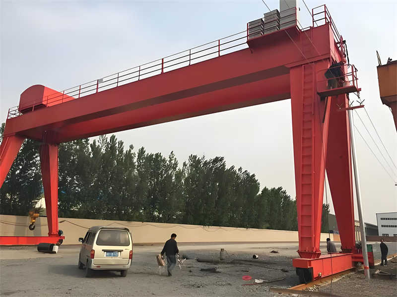
The 5-320 ton gantry crane is a large-scale lifting device employing a gantry-type structural design, possessing strong load-bearing capacity and stability. This equipment is widely used in locations such as ports, docks, and railway freight yards, suitable for the hoisting and handling of various heavy objects. The gantry crane features a modular design, facilitating transportation and installation, while also offering high operational efficiency and safety. Its structure mainly includes the main girder, end beams, traveling mechanism, and hoisting mechanism, providing high strength and stability.
The technical parameters of the 5-320 ton gantry crane include rated lifting capacity, span, lifting height, duty class, etc. The rated lifting capacity ranges from 5 to 320 tons, the span can be customized according to actual requirements, and the lifting height is typically 10 to 30 meters. The duty class ranges from A5 to A7 based on usage frequency and load conditions, meeting the needs of different working conditions. The equipment’s operating speed is divided into three types: hoisting, gantry travel, and trolley travel; specific values should be referred to in the product technical manual.
Table: Main Technical Parameters of 5-320 Ton Gantry Crane
| Parameter Category | Parameter Range/Value | Technical Description | Applicable Scenarios | Structural Features | Customization Options |
|---|---|---|---|---|---|
| Rated Lifting Capacity | 5-320 tons | Select different specifications based on load requirements | Ports, Docks, Railway Yards | Reinforced main girder & end beam design | Customizable capacity range |
| Span | Customizable (Typical 10-50m) | Adjust span according to site requirements | Large Industrial Plants, Logistics Parks | Modular structure for easy transport | Supports non-standard span design |
| Lifting Height | 10-30 meters | Standard configuration meets most operational needs | Shipyards, Heavy Equipment Assembly | Wire rope/chain drive system | Extendable to 40 meters |
| Duty Class | A5-A7 | Classified per ISO4301 standard for usage intensity | High-frequency lifting sites | Fatigue-resistant steel structure | Upgradable to A8 class |
| Operating Speed | Hoisting: 3-15 m/min | Multi-speed control | Container handling, component moving | Frequency conversion drive system | Adjustable speeds |
| Environmental Adaptability | -40°C ~ +50°C | Special anti-corrosion treatment / sand-proof design | Extreme climate regions | Sealed electrical components | Optional environmental protection package |
Table: Gantry Crane Application Scenarios vs. Function Comparison
| Application Field | Typical Tasks | Equipment Configuration Requirements | Technical Advantage | Representative User Groups | Safety Standards |
|---|---|---|---|---|---|
| Ports & Terminals | Container Handling | High Hoisting Speed + Auto Positioning | 30% Operational Efficiency Increase | International Freight Ports | ISO 12485-1 Certification |
| Railway Yards | Heavy Cargo Transfer | Large Span + Dual Hook System | Multi-location simultaneous operation | Railway Logistics Centers | EN 15011 Certification |
| Shipyards | Hull Section Lifting | Ultra-high Lifting Height + Precision Control | Millimeter-level positioning accuracy | Shipbuilding Enterprises | GOST Certification |
| Power Construction | Transformer Installation | High Tonnage + Anti-Sway System | Heavy load stability factor ≥1.5 | Energy Engineering Companies | ASME B30.2 Standard |
| Industrial Plants | Production Line Maintenance | Medium/Low Duty Class + Compact Design | 40% Space Utilization Increase | Automotive Manufacturers | FEM 9.511 Standard |
| Logistics Parks | Bulk Cargo Turnover | All-weather operation + Remote Monitoring | Supports unmanned operation | 3rd Party Logistics Providers | GB/T 14405-2011 |
The 5-320 ton gantry crane is suitable for large industrial plants, logistics parks, shipyards, and other locations. Its high load-bearing capacity and stability make it the preferred choice for hoisting heavy equipment. The gantry crane can also be used for operational scenarios such as container handling and large component assembly, possessing strong environmental adaptability. Furthermore, this equipment can be customized according to the requirements of different working conditions to satisfy users’ diverse needs.
The main girder is the core load-bearing component of the bridge crane, and its structural design plays a decisive role in the performance and stability of the entire machine. Modern bridge crane main girders typically employ box-type or truss-type designs, both of which provide extremely high rigidity and excellent anti-bending capability. The box-type main girder, with its enclosed cross-sectional shape, incorporates multiple internal transverse and longitudinal stiffening ribs. These ribs not only enhance the local rigidity of the girder but also effectively prevent deformation of the box under heavy load conditions, ensuring the girder maintains stable geometry and load-bearing capacity even under long-term, high-intensity use. The truss-type main girder optimizes the load distribution among members, utilizing interconnected rods forming a bridge-like structural system. This allows loads to be dispersed and transferred through various members when external forces are applied, significantly reducing the overall structural weight while maintaining necessary strength. This design gives the truss girder better economy and adaptability, especially advantageous in large-span applications. Whether box-type or truss-type, the girder surfaces undergo special anti-corrosion treatment processes, such as anti-rust paint, thermal spray zinc coating, or use of stainless steel, to effectively resist corrosive agents in the environment, delay structural aging, thereby greatly increasing the service life of the main girder and ensuring long-term stable operation of the crane.
The legs are crucial components for crane support and stability, configured based on the span size. Rigid legs are rigidly connected to the main girder, bearing the main load; flexible legs allow a certain degree of displacement to accommodate thermal expansion and contraction caused by temperature changes. Travel mechanisms are installed at the bottom of the legs, supporting the movement of the entire gantry crane.
The hoisting mechanism is one of the core components of the crane, primarily used for lifting heavy loads. It mainly consists of an electric motor, reducer, drum, wire rope, and hook. The motor drives the drum to rotate via the reducer, enabling the winding and unwinding of the wire rope. The wire rope is made of high-strength material to ensure hoisting safety. The hook is equipped with an anti-release device to prevent accidental load detachment.
The travel mechanism includes both gantry travel and trolley travel parts. The gantry travel mechanism drives the gantry crane along the track, while the trolley travel mechanism controls the transverse movement of the lifting appliance on the main girder. The travel mechanism employs variable frequency speed control technology to achieve smooth starting and braking. The travel mechanism is another key part of the crane, used to control the crane’s movement and position. It includes both gantry travel and trolley travel parts. The gantry travel mechanism drives the entire gantry crane along the track via a drive device, while the trolley travel mechanism achieves precise position control by managing the transverse movement of the lifting appliance on the main girder. The travel mechanism uses advanced variable frequency speed control technology, making the crane’s starting and braking processes smoother, while also improving the crane’s operational efficiency and service life.
Before installing any equipment or machinery, comprehensive and meticulous preparatory work must be carried out to ensure the smooth progress of the installation and the safe and reliable operation of the final product. First, carefully inspect all components for completeness, absence of damage, and correct quantity, including but not limited to foundation rails, legs, main girder, hoisting mechanism components, travel mechanism components, and other necessary ancillary facilities. Verify that the installation position, dimensional specifications, and fixation of the foundation rails comply with the design drawings and technical specifications, ensuring parameters such as flatness, straightness, and span of the rails meet the basic conditions for equipment installation and operation.
Thoroughly clean the installation site to ensure the work area is free of debris, obstacles, or other potential safety hazards that might affect hoisting and equipment operation. Based on the equipment weight and dimensions, plan and prepare corresponding lifting equipment and tools in advance, such as cranes, forklifts, jacks, slings, etc., and ensure these devices are in good working condition. Develop a detailed installation process plan, clarifying tasks and responsibilities at each stage to facilitate orderly execution of various operations during installation.
The basic sequence of equipment installation typically follows the principle of first fixing the foundation parts, then progressively assembling the main structure, and finally installing movable or adjustable components. Specifically for the installation of heavy equipment like cranes, begin with the positioning and installation of the leg sections, ensuring a firm and reliable connection between the legs and the foundation rails. Use high-strength bolts or other suitable methods to tightly connect the legs to the main girder, forming a stable support structure.
Next is the hoisting of the main girder. Using the pre-prepared lifting equipment and tools, hoist the main girder steadily and place it accurately in the predetermined position. Pay attention to checking the alignment accuracy of the connection interfaces between the main girder and the legs, and whether all connecting bolts are fully tightened. After completing the main girder positioning, proceed with the installation and debugging of the hoisting mechanism, including but not limited to the assembly and adjustment of key components such as the electric hoist, hydraulic system, and brake devices, ensuring these mechanisms function normally and meet safety performance standards.
Finally, install the travel mechanism. The travel mechanism usually includes drive devices, travel wheel sets, etc. Assemble these into the designated positions according to the design requirements, and use precision instruments like sensors and theodolites to accurately measure and adjust the verticality, levelness, and straightness of the travel path, ensuring the equipment can perform various actions stably and reliably after being put into use.
The commissioning phase consists of two important parts: no-load test run and load test run. The no-load test run is a preliminary test conducted without loading any cargo, aiming to check whether various mechanisms (including but not limited to hoisting, travel, and slewing mechanisms) can start, accelerate, decelerate, and stop smoothly. Check whether safety protection devices like limit switches and travel switches actuate accurately at predetermined positions, preventing abnormal damage to the equipment due to overload or misoperation. The load test run is an in-depth test performed while gradually increasing the load weight, focusing on verifying key indicators such as the equipment’s hoisting capacity, travel speed, and braking performance.
Verify the load capacity and lifting accuracy of the hoisting mechanism by repeatedly lifting and lowering loads; test the operational efficiency and stability of the equipment under load through long-distance travel and frequent directional changes; observe and analyze speed variations, vibration amplitude, temperature changes, etc., of the equipment under load to determine if its working performance is normal; it is particularly important to strictly enforce safety regulations during commissioning, prohibiting any personnel from staying under suspended loads or performing other unrelated tasks to prevent accidents.
If abnormal noises are heard during equipment operation, or excessive vibration is observed, the equipment must be stopped immediately, and various components that might cause the problem should be carefully inspected, including but not limited to loose connections, bearing condition, and effectiveness of the lubrication system. After completing all commissioning procedures, a comprehensive re-inspection and tightening of all parts of the equipment must be carried out, ensuring all connection points are tightened according to the specified torque to prevent loosening caused by vibration or stress; conduct a thorough check of the electrical control system, including but not limited to power stability testing, inspection of component interface contacts, and verification of protection device sensitivity.
Before commencing any operation, carefully inspecting the wire rope is crucial. The wire rope is a vital component of the crane; once wire breakage or severe wear occurs, it may lead to equipment failure or safety incidents. Therefore, operators need regular professional training to master the ability to identify potential risks in wire ropes. Additionally, the hook, as the component directly bearing the load, directly affects operational efficiency and safety. Operators should check if the hook rotates smoothly, for any jamming, and confirm the proper function of all limit switches. The track is the path for crane operation; it must be ensured that the track is free of obstructions hindering movement. Checking the insulation performance of the electrical system is also essential to avoid electrical faults like leakage causing accidents.
Before starting the crane, the operator should sound an alarm to alert surrounding personnel and confirm the safety of the work area. During operation, the controller should be operated smoothly, avoiding sudden acceleration or deceleration that could impact the load and equipment. During lifting, the load must be kept stable, and side pulling or swinging of the load is prohibited to prevent equipment tipping or load falling accidents.
In certain special circumstances, operators need to take corresponding measures: during high wind conditions, operations should be stopped and the gantry crane anchored and secured to prevent wind-induced movement or tipping. When the load is close to the rated capacity, the controller should be operated slowly to avoid equipment damage or safety incidents due to overload. In case of sudden power failure, immediately cut off the power and manually release the brake to lower the load safely to the ground to prevent accidents.
After completing the work, the operator needs to raise the hook to the specified height and park the trolley at the designated position to facilitate subsequent inspection and maintenance. Simultaneously, cut off the main power supply and clean the work site, maintaining the tidiness and safety of the work area. Furthermore, fill out the equipment operation log, recording any problems discovered during the shift and their solutions, to provide reference for subsequent equipment maintenance and management.
Check the lubrication condition of the wire rope daily to ensure it remains well-lubricated, reducing wear and corrosion. Inspect the track for any debris or obstacles and clean them immediately to ensure smooth equipment operation. Check for loose bolts on various mechanisms and tighten them appropriately to prevent abnormal vibrations or failures caused by looseness. Replenish lubricating oil based on equipment usage, ensuring good internal lubrication and smooth operation. Observe electrical wiring for aging or damage, and address any issues promptly to ensure the safety and reliability of the electrical system.
Conduct a comprehensive monthly inspection of the equipment’s hoisting mechanism, including performance tests of key components such as brakes, motors, and reducers, ensuring their stable and reliable operation. Quarterly, replace the reducer lubricating oil and clean the filter to prevent equipment operational faults caused by oil deterioration or blockage. Annually, perform non-destructive testing on the equipment’s metal structure to assess the overall condition and identify and address potential safety hazards.
Table: Periodic Maintenance Items and Schedule
| Maintenance Item | Inspection/Operation Content | Frequency | Key Parts/Materials | Standards/Precautions | Related Tools/Accessories |
|---|---|---|---|---|---|
| Wire Rope Lubrication | Check lubrication, replenish grease | Daily | Wire Rope, Grease | Reduce wear & corrosion | Grease Gun, Cleaning Cloth |
| Track Cleaning | Remove debris or obstacles | Daily | Track, Cleaning Tools | Ensure smooth operation | Broom, Vacuum |
| Bolt Tightening | Check & tighten mechanism bolts | Daily | Bolts, Wrench | Prevent abnormal vibration | Torque Wrench |
| Hoisting Mech. Inspection | Test brake, motor, reducer performance | Monthly | Brake, Motor, Reducer | Ensure reliable operation | Multimeter, Vibration Meter |
| Reducer Oil Change | Change oil, clean filter | Quarterly | Lubricating Oil, Filter | Prevent oil degradation/blockage | Oil Pump, Filter Element |
| Structure NDT | Assess condition, detect hidden defects | Annually | NDT Tester, Metal Structure | Identify safety hazards | Ultrasonic Flaw Detector |
| Wire Rope Replacement | Replace if broken wires exceed standard | As Needed | Wire Rope, Clamps | Ensure safety | Wire Rope Cutter |
| Brake Lining Replacement | Replace if worn to limit thickness | As Needed | Brake Lining, Brake Disc | Maintain braking performance | Brake Adjustment Tools |
Table: Wear Parts Replacement Methods & Standards
| Wear Part Name | Replacement Standard/Trigger Condition | Key Replacement Steps | Required Tools/Accessories | Precautions | Reference Standard/Basis |
|---|---|---|---|---|---|
| Wire Rope | Broken wires exceed specified standard | Remove old rope, install new rope, adjust tension | Wire Rope Cutter, Tension Gauge | Use OEM parts, ensure precise dimensions | GB/T 5972-2016 |
| Brake Lining | Worn to limit thickness (e.g., 3mm) | Dismantle brake, replace lining, calibrate gap | Brake Adjustment Tools, Caliper | Avoid oil contamination of friction surface | JB/T 6406-2006 |
| Lubricating Oil | Oil deteriorated/contaminated (viscosity/impurities超标) | Drain old oil, clean tank, refill new oil | Oil Pump, Filter Element, Viscometer | Select oil grade per manual | ISO 4406 |
| Filter | Clogged or differential pressure exceeds set value | Dismantle housing, replace element, test seal | Filter Wrench, Pressure Gauge | Check differential pressure regularly | _ |
| Electrical Wiring | Aged, damaged, or insulation resistance below standard | Sectional check, replace damaged cable, test insulation | Multimeter, Insulation Tape | De-energize operation, prevent short circuit | GB 5226.1-2019 |
| Bolts | Loose or threads damaged | Remove old bolt, apply threadlocker, tighten new bolt | Torque Wrench, Thread Repair Kit | Tighten to standard torque | DIN 912 |
For wear parts like wire rope, if the number of broken wires is found to exceed the specified standard, use should be stopped immediately and the rope replaced to ensure safety. For braking system components like brake linings, they should be updated promptly when worn to the limit thickness to ensure good braking performance. When replacing parts, original manufacturer parts must be used to ensure the replacement parts are dimensionally accurate and performance-matched, maintaining the overall stability and safety of the equipment.
All operators must undergo professional training and hold valid qualification certificates, familiar with the performance characteristics, operating procedures, and limit parameters of the equipment they operate. During operations, all safety regulations must be strictly implemented, and overloaded operations are strictly prohibited to prevent equipment damage or accidents. Using the hook to drag heavy objects is forbidden to prevent load detachment or loss of control. During operation, operators should concentrate fully on the task and must not engage in unrelated activities, such as answering phones or chatting.
Operators must wear personal protective equipment compliant with national standards, such as safety helmets and shoes with good anti-slip properties, to effectively reduce injury in case of an accident. Non-operators are prohibited from entering the work area to prevent misuse or accidental injury. Signalers should use standard hand signals or two-way radios for communication to ensure instructions are clear and unambiguous, avoiding operational errors due to miscommunication.
The work area should be demarcated with clear warning lines to prevent unauthorized personnel from entering. During night operations, ensure adequate lighting so operators can clearly identify the work environment and object status. Do not pile materials on both sides of the track to ensure sufficient operating space and avoid obstructions affecting normal equipment operation. The foundation bearing capacity must meet equipment requirements to prevent safety hazards like equipment tilting or subsidence due to foundation issues. Operations must cease immediately during thunderstorm weather to ensure the safety of personnel and equipment.
When equipment failure occurs, the operator should immediately stop operation and cut off the power supply to ensure safety. To address potential emergencies, detailed emergency plans should be prepared in advance and drills conducted regularly. This not only enhances employee safety awareness but also ensures a swift and effective response in emergencies. Furthermore, necessary first-aid equipment, such as first-aid kits and fire extinguishers, should be available for initial treatment in case of accidents. Also, clearly mark escape routes and assembly points to ensure personnel can evacuate quickly to safety in an emergency.
Contact our crane specialists
Send us a message and we will get back to you as soon as possible.