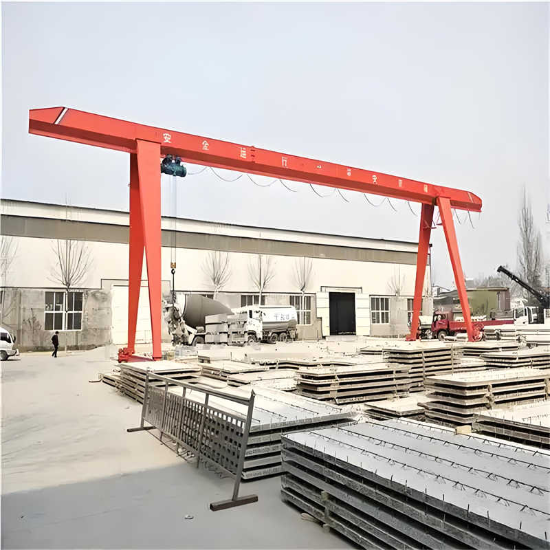
This installation plan is formulated for the installation project of a 5-ton gantry crane, suitable for lifting operations in locations such as factories, ports, and construction sites. The gantry crane has a rated lifting capacity of 5 tons. The span is determined according to actual site requirements, and the lifting height is typically around 9 meters. Specific parameters can be adjusted based on actual project needs.
II. Basis for Compilation
National Standards and Industry Codes:
Safety Regulations for Lifting Appliances (GB 6067-2010)
General Gantry Cranes (GB/T 14406-2011)
Code for Construction and Acceptance of Lifting Equipment Installation Engineering (GB 50278-2010)
Technical Specification for Safe Use of Construction Machinery (JGJ 33-2012)
Design Documents: Gantry crane design drawings, technical specifications, and installation manuals provided by the supplier.
Site Conditions: Compiled based on the actual conditions of the installation site, including geology, environment, and power supply.
III. Construction Preparation
(1) Personnel Organization
Project Manager: 1 person, responsible for overall coordination and safety management.
Technical Manager: 1 person, responsible for technical guidance and quality acceptance.
Installation Workers: 4-6 persons, responsible for structural component hoisting and assembly.
Electrician: 1 person, responsible for electrical system installation and debugging.
Safety Officer: 1 person, responsible for on-site safety supervision.
(2) Equipment and Materials
Main Equipment:
Two 16-ton truck cranes (for dual-crane lifting of the main girder).
Four 3-ton chain hoists (for auxiliary hoisting and adjustment).
One set each of electric welding machine and gas cutting equipment (for on-site welding and cutting).
Materials:
Structural components such as the main girder, legs, end beams, and travel mechanisms (provided by the supplier).
Connecting components such as anchor bolts, high-strength bolts, and shim plates.
Electrical components such as cables, control boxes, and sensors.
Maintenance materials such as anti-rust paint and lubricating oil.
(3) Site Conditions
Foundation Requirements:
Concrete foundation strength grade not lower than C30, with a compacted and level base.
Pre-embedded track steel plates and rails must be firmly connected. Track gauge deviation ≤ ±10mm, track level height deviation ≤ 10mm.
Site Requirements:
The installation area should be flat, open, unobstructed, and the ground bearing capacity must meet the crane operation requirements.
The power supply capacity must meet the gantry crane’s operational demands, equipped with an independent distribution box.
(4) Procedure Formalities
Submit the installation notification to the local special equipment safety supervision department.
Submit design documents, the installation plan, and construction personnel qualification certificates.
IV. Installation Process
(1) Track Installation and Re-inspection
Track Laying:
Position the track centerline according to the design drawings, using a theodolite to calibrate straightness.
Fix the rails to the pre-embedded steel plates with clamp plates and bolts, installing one set of clamps every 2 meters.
Track Re-inspection:
Check track gauge, levelness, and joint gaps to ensure compliance with code requirements.
Record re-inspection data and submit it to the supervision unit for acceptance.
(2) Structural Component Assembly
Leg and Bottom Beam Assembly:
Connect the rigid legs, flexible legs, and upper/lower beams on the ground using high-strength bolts. Bolt preload must meet design requirements.
Install the electrical operator’s cab platform, adjust its position, and fix the support frame.
Main Girder Assembly:
Due to transport limitations, the main girder needs on-site assembly. Hoist single girder sections onto temporary supports and connect them via flange bolts, ensuring bolt tightening torque meets standards.
After assembly, check the main girder straightness; deviation should be ≤ L/1500 (L is the girder length).
(3) Integral Hoisting
Leg Hoisting:
Use a 16-ton truck crane to hoist the legs. Select lifting points near the end beams, approximately 5 meters from the centerline.
Use taglines to control direction during hoisting. Slowly lower onto the foundation pre-embedded parts. After preliminary positioning, insert anchor bolts and temporarily secure.
Main Girder Hoisting:
Use the dual-crane lifting method, with two cranes simultaneously lifting both ends of the main girder.
Select lifting points near the mid-span of the main girder. Each crane’s load should not exceed 80% of its rated capacity.
Before lifting, check that slings have no sharp bends or knots. The signal person gives unified commands. Hoisting speed should be controlled at 1.5-2 m/min.
After hoisting the main girder above the legs, slowly lower it to align the flange bolt holes. Insert high-strength bolts and perform initial tightening.
(4) Structural Connection and Adjustment
Leg and Main Girder Connection:
Connect the legs and main girder flanges using high-strength bolts. Tighten to the design torque in three steps following a diagonal sequence.
Check the connection surface gap; accept if the gap is ≤ 0.5mm using a feeler gauge.
Travel Mechanism Installation:
Hoist the gantry travel mechanism onto the tracks. Adjust the flange-to-rail clearance to 2-5mm.
Install rail clamps, ensuring tight contact between the clamps and the rails.
(5) Electrical System Installation
Cable Laying:
Lay power cables, control cables, and signal cables according to the design drawings, avoiding cross-interference.
Protect cables with conduits; bending radius should be ≥ 6 times the cable outer diameter.
Electrical Equipment Installation:
Install components such as the control box, resistors, and limit switches. Secure firmly and ensure reliable grounding.
Connect motor and brake wiring. Check phase sequence to ensure correct rotation direction.
Grounding and Lightning Protection:
Grounding resistance should be ≤ 4Ω. Measure periodically and record.
Install lightning rods. Connect down conductors reliably to the grounding grid.
(6) Safety Device Installation
Limit Devices:
Install hoisting height limiters, gantry travel limiters, and trolley travel limiters. Debug to ensure sensitive and reliable operation.
Buffers:
Install polyurethane buffers at both ends of the tracks to absorb impact energy.
Overload Protection:
Install load sensors and set the overload alarm threshold (110% of the rated load).
V. Debugging and Acceptance
(1) No-load Debugging
Operating Mechanism Tests:
Perform no-load operation of the hoisting, gantry travel, and trolley travel mechanisms separately. Check if starting and braking are smooth.
Measure travel speeds; deviation should be ≤ ±5%.
Electrical System Tests:
Check that the direction of movement for each mechanism matches the control buttons and that the emergency stop button is effective.
Test the response time of safety devices such as limit switches and overload protection.
(2) Load Testing
Static Load Test:
Suspend a load of 1.25 times the rated capacity (6.25 tons) 100-200mm above the ground for 10 minutes.
Check structural components for permanent deformation, welds for cracks, and connection bolts for looseness.
Dynamic Load Test:
Suspend a load of 1.1 times the rated capacity (5.5 tons). Perform combined actions including hoisting, braking, traveling, and slewing (if applicable).
Test duration should be ≥ 1 hour. Check that all mechanisms operate normally without abnormal vibration or noise.
(3) Handover and Acceptance
Self-inspection:
The installation unit conducts a comprehensive inspection of the gantry crane, compiling debugging records and quality certification documents.
Supervision Acceptance:
The supervision unit organizes the acceptance, checking installation quality, safety devices, and test reports.
Special Equipment Institute Inspection:
Apply to the Special Equipment Inspection Institute for supervisory inspection. Obtain the inspection certificate and then apply for the use registration certificate.
VI. Safety Measures
Personnel Protection:
Installation personnel must wear safety helmets, safety belts, and anti-slip shoes. Install safety nets for work at height.
Equipment Inspection:
Daily inspection of cranes, slings, welding machines, and other equipment to ensure good performance.
Site Management:
Set up warning lines around the installation area; unauthorized personnel are prohibited from entering.
Stop outdoor work in case of wind force above Level 6 or rain/snow weather.
Emergency Plan:
Develop emergency plans for accidents such as collapse, electric shock, and falls from height. Conduct regular drills.
VII. Environmental Protection
Noise Control:
Select low-noise equipment. Prohibit high-noise operations at night.
Waste Disposal:
Sort and collect waste such as metal scraps and paint cans for recycling by professional units.
Dust Prevention:
Spray water for dust suppression at the construction site. Cover transport vehicles with dust-proof nets.
This plan ensures the safe and efficient commissioning of the 5-ton gantry crane through a systematic installation process, strict quality control, and comprehensive safety measures, providing reliable support for the construction project.
Contact our crane specialists
Send us a message and we will get back to you as soon as possible.