In modern industrial production, the efficiency and safety of material handling equipment directly impact operational efficiency. The 5t electric hoist wall-travelling crane, a typical heavy-duty lifting machine, combines the vertical lifting capabilities of an electric hoist with the horizontal movement of a wall-travelling track, creating a unique spatial working solution. This equipment utilizes a modular design concept, with each functional unit rigorously tested for compatibility, ensuring stable operation at rated loads. Its compact structure makes it ideal for material transfers between factory columns or in specialized work areas, effectively addressing corner operations that are difficult for traditional bridge cranes. The control system integrates multiple safety interlock mechanisms, complying with national safety technical regulations for special equipment and providing reliable operator protection.
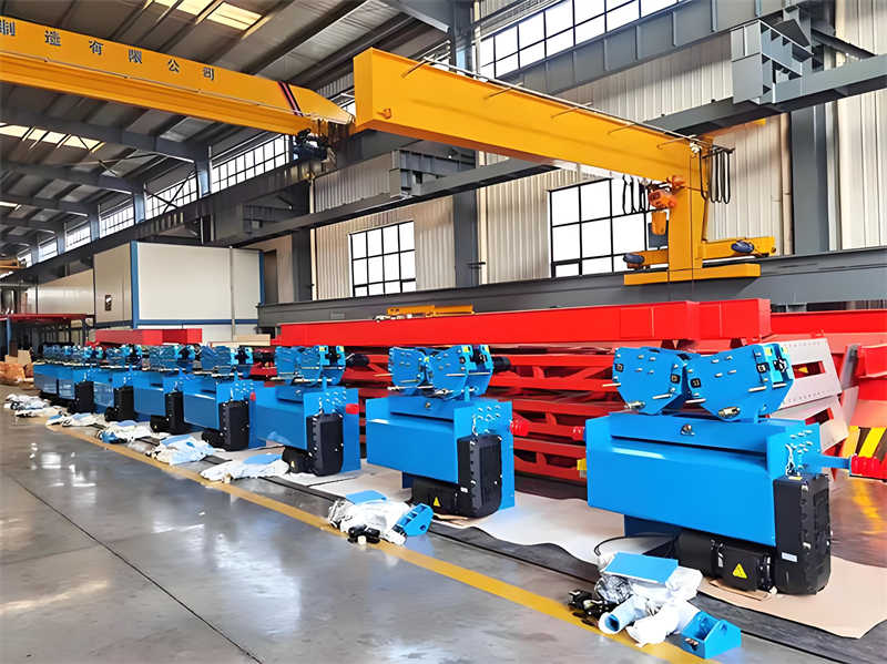
The 5t electric hoist wall-travelling crane is an efficient, practical, lightweight lifting device designed for confined spaces. It operates horizontally along a wall track, boasting a compact structure and smooth operation. Using an electric hoist as its lifting mechanism, this crane has a rated lifting capacity of 5 tons and meets short- to medium-distance material handling needs. This crane is suitable for various confined environments, such as factories and warehouses. It improves material handling efficiency and reduces labor intensity, making it an indispensable piece of equipment in modern production lines.
The 5t electric hoist wall-travelling crane features a modular design for easy installation and maintenance. It features dual-speed control to meet diverse lifting requirements. The low headroom design reduces vertical space usage, making the crane more suitable for a variety of environments. The intelligent limit function effectively prevents overwinding accidents.
The 5t electric hoist wall-travelling crane is suitable for use in dry, non-explosive indoor environments with an ambient temperature of -20°C to 40°C and a relative humidity of 85% or less. During installation and operation, ensure that the wall surface on which the track is mounted meets load-bearing standards and has a concrete strength grade of at least C20. Do not use this equipment in corrosive, flammable, or explosive environments, or in environments with strong electromagnetic interference.
The 5t electric hoist wall-travelling crane complies with GB/T 3811-2008 “Crane Design Code” and JB/T 2603-2008 “Technical Requirements for Electric Hoist Gantry Cranes.” It is CE certified and meets ISO 4309 wire rope scrap standards. Key components are made of Q345B steel, and the motor has an IP54 protection rating. These certifications and standards ensure the stability and safety of this equipment, meeting user needs.
The core drive component of the electric hoist is a hoist motor with a conical rotor brake structure. This design enables automatic braking in the event of a power outage, ensuring a rapid halt to the hoisting operation in an emergency and effectively preventing accidents. The drum mechanism features a spiral groove guide system to ensure the wire rope remains aligned during operation, preventing tangling caused by long-term use and thus extending the wire rope’s service life. The hook assembly is equipped with an advanced tongue-type anti-drop device. This simple and reliable structure effectively prevents the risk of the hook accidentally falling off, greatly improving operational safety and efficiency.
The wall track system consists of an H-shaped steel track, a trolley, and a buffer device. The H-shaped steel track is connected to the embedded wall components with high-strength bolts, ensuring track stability and safety. The trolley features a four-wheel drive structure, with one drive wheel covered with polyurethane to reduce noise and enhance driving stability.
The system is primarily ground-operated and comes standard with a 0.5t pull-wire flashlight and electric door controller. To enhance operational convenience and flexibility, an optional wireless remote control system (operating in the 2.4GHz frequency band) is available, extending the control distance to 50 meters or less. A thermal overload relay and phase sequence protector are installed within the electrical box to ensure timely power cutoff in the event of an abnormality, protecting the equipment from damage.
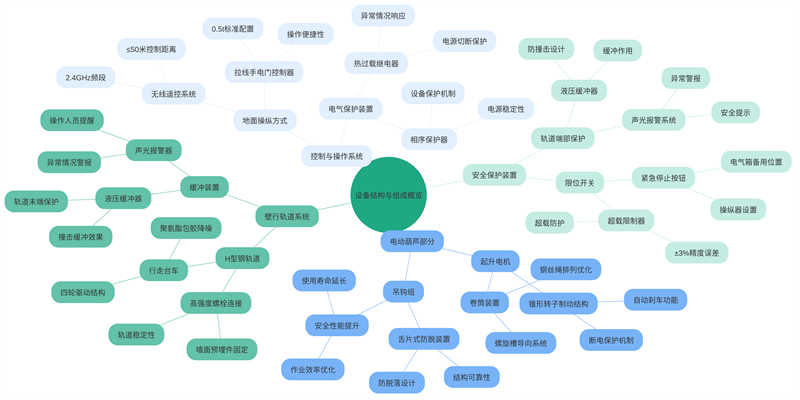
In addition to standard limit switches, an overload limiter with an accuracy of ±3% has been added, effectively preventing safety hazards caused by overloading. Furthermore, hydraulic buffers are installed at the ends of the track to cushion the equipment when it approaches the end of the track, preventing damage from impact. Furthermore, audible and visual alarms sound an alarm in the event of an abnormality, prompting the operator to take immediate action. To further enhance safety, an emergency stop button is not only located on the manipulator, but also in a backup position on the electrical box, ensuring that power can be quickly disconnected in any event.
Before formal installation, a comprehensive and thorough inspection of the equipment is essential to ensure a smooth installation process. First, check the packing list to confirm that all parts and accessories are present and complete. Next, check the position of the embedded parts on the track, ensuring deviations within 5mm to ensure accurate and stable track installation. The wire rope of the electric hoist should be carefully inspected for rust or broken wires. According to regulations, the number of broken wires within a length of 10 times the wire diameter should not exceed 5% to ensure the strength and safety of the wire rope. Furthermore, the track straightness error must be measured and should not exceed 1/1500 to ensure smooth and accurate operation of the equipment.
Track Installation: Use a high-precision laser level to accurately measure the track levelness and ensure that the level error is within the allowable range (≤3mm/10m). To ensure track stability, all bolted connections must be torqued to the required design. In this installation, bolts will be tightened to 120% of the design value.
Hoist Installation: To ensure continuity and integrity during the hoist installation process, an auxiliary crane will be used for the entire hoist installation. During the installation process, disassembly of key components such as the reducer is strictly prohibited to maintain the overall performance and safety of the hoist.
Electrical Wiring: When selecting power cables, strictly adhere to regulations and use wire with a cross-sectional area of at least 4mm² to ensure a stable and sufficient power supply. The ground resistance test is also essential, and its value must be controlled below 4Ω to ensure the safety of operators and the normal operation of equipment.
No-load Test Run: A two-hour no-load test run is conducted, closely monitoring the operating conditions and temperature rise of each mechanism. Regulations require that the motor temperature rise should not exceed 65K, and the reducer temperature rise should not exceed 45K to ensure the equipment’s reliability and stability during long-term operation.
Rated Load Test: A test is conducted under the equipment’s rated load. Professional measurement methods are used to determine whether the static deflection of the main beam meets the design requirements (≤L/800), thereby verifying the equipment’s load-bearing capacity and structural safety under actual operating conditions.
After installation, a detailed “Installation Acceptance Record Form” must be completed to thoroughly verify all equipment performance indicators. Special attention should be paid to checking the braking slippage, the presence of any sticking in the operating mechanism, and whether the stopping distance after the limit switch is triggered meets regulatory requirements. Only when all inspection items meet design standards and acceptance requirements can the formal acceptance report be signed, confirming that the equipment has been installed satisfactorily and is ready for normal operation.
Before turning on the machine, first ensure the main power switch is turned on and closely monitor the voltage meter. Ideally, it should remain stable at around 380V, with a fluctuation range of no more than ±10%. Next, press the power button on the control box. The indicator light should turn from red to green, indicating that the machine has successfully powered on and entered standby mode. To ensure proper braking system performance, perform three tests according to operating procedures, lifting the load to a specified height and then lowering it smoothly. This series of maneuvers verifies the sensitivity and effectiveness of the braking system.
When performing lifting operations, always keep the load perpendicular to the ground. Slanting operations are strictly prohibited to prevent damage to the lifting equipment and the load. For long-distance movements, inching mode is recommended, with each continuous operation lasting no more than 30 minutes to avoid motor overheating and potential safety hazards. If a load needs to remain suspended in the air for more than 5 minutes, the mechanical locking device must be activated and functioning properly to ensure safe operation. Special Situation Handling
In the event of a sudden power outage, the operator should quickly reset all controller parameters to zero to ensure the equipment is in a safe state. If the wire rope is found to have jumped out of its normal slot, immediately disconnect the power supply and use specialized tools to reset the wire rope. Manual intervention or adjustments are strictly prohibited to prevent accidental injury.
After completing a lifting operation, be sure to park the hoist in its designated location to ensure it is secure and stable. Before disconnecting the power supply, carefully check that all mechanisms are in the non-operating state to prevent the equipment from idling or accidentally starting up. Especially during rainy seasons, the equipment should be properly protected, such as covered with a rainproof sheet, to extend its service life and ensure safety upon next startup.
Operators or maintenance personnel must perform thorough daily inspection and maintenance of the equipment. For example, critical components such as wire ropes must be inspected for wear, including but not limited to diameter reduction, to ensure compliance with specified standards (e.g., diameter reduction must not exceed 7%). Brake pad thickness is also a key inspection priority, requiring at least 50% of its original thickness to ensure braking effectiveness and safety. Furthermore, the track treads must be cleaned regularly to maintain good contact, and the use of corrosive cleaning agents is strictly prohibited to prevent damage to the equipment.
Periodic maintenance and care is required every 500 operating hours. During this time, the reducer lubricant should be replaced, using L-CKC220 lubricant in accordance with GB 5903-2011. The motor bearing clearance should also be checked to ensure radial clearance does not exceed 0.15mm to ensure stable and reliable operation. Annual inspections are even more important, requiring qualified and certified personnel to conduct a comprehensive inspection and load test of the equipment to ensure it is in good working condition.
During equipment operation, you may encounter some common fault codes. For example, the E01 fault code indicates a wiring problem with the phase sequence protector, requiring inspection and verification of correct wiring. The E05 fault code indicates that the overload limiter needs to be reset and the load verified to ensure compliance. The E12 fault code indicates wear on the travel wheel bearings, requiring replacement. During fault diagnosis and troubleshooting, adhere to appropriate operating procedures and safety precautions.
Table: Common fault codes and troubleshooting methods
| Fault Code | Fault description | Possible causes | Troubleshooting | Safety Precautions | Relevant standards/specifications |
| E01 | Phase sequence protector abnormality | Incorrect wiring or phase sequence | Check and reconnect the wires to ensure the phase sequence is correct | Power off and use a test pen to confirm that there is no electricity | GB/T 14048.1-2012 |
| E05 | Overload limiter triggered | Load exceeds limit or sensor fails | Reset the limiter and check the actual load | Forced reset is prohibited and the cause of overload needs to be checked. | GB 6067.1-2010 |
| E12 | Travel wheel bearing wear | Insufficient lubrication or fatigue damage | Replace the bearing with a new one and add the specified grease | Use special tools to disassemble and avoid damaging the journal | JB/T 9005.1-2014 |
| _ | Brake failure | Pad wear or hydraulic leak | Check the thickness of the gasket (≥50% of the original thickness) and add hydraulic oil | Hang maintenance warning signs and prohibit manned testing | GB/T 3811-2008 |
Table: Maintenance standards and cycles for key components
| Part Name | Inspection items | Maintenance standards | Maintenance cycle | Operating specifications | Replacement Standard |
| Wire rope | Diameter wear | ≤7% original diameter | Daily inspection | Use a caliper to measure and record the amount of wear | The number of broken wires exceeds 10% or the diameter reduction exceeds 7% |
| Brake pads | Remaining thickness | ≥50% original thickness | Daily inspection | Remove oil stains and measure the thinnest part | Insufficient thickness or cracks |
| Reducer lubricant | Oil quality | L-CKC220 model | 500 working hours | Drain the old oil, clean it and add new oil | The oil is black or contains metal chips |
| Motor bearings | Radial clearance | ≤0.15mm | 500 working hours | Measuring with a dial indicator | Excessive clearance or abnormal noise |
| Track tread | Cleanliness | No oil/rust | Daily cleaning | Do not use corrosive cleaning agents | Pit or deformation |
When performing equipment maintenance, relevant safety regulations and operating procedures must be followed. For example, during maintenance, warning signs such as “No Operation” or “Under Maintenance” should be displayed prominently on the equipment to prevent unauthorized personnel from operating it. For the critical operation of replacing wire ropes, ensure that the new wire rope has the same lay direction as the original one and that the new rope is pre-stretched before use, typically to 125% of its rated value, to eliminate internal stress and increase its service life. Furthermore, all maintenance operations should be performed with the equipment stopped and the main power disconnected to ensure personnel safety.
All crane operators must undergo professional training and obtain a nationally recognized “Special Equipment Operator Certificate” with the project code Q2. This ensures that operators possess the appropriate operating skills and safety knowledge. Operators must also receive at least eight hours of operator training provided by the equipment manufacturer to familiarize themselves with the equipment’s performance specifications, operating procedures, and emergency response measures. Personnel under the age of 18 lack the necessary judgment and physical strength to operate this equipment. Color blind individuals may not be able to accurately identify signal lights or other color markings, potentially leading to safety accidents, and are therefore prohibited from operating this equipment.
When lifting liquid metal, the following safety regulations must be strictly adhered to: First, the lifting height must be controlled within 1 meter to ensure the stability of the load and prevent the risk of swaying and falling due to excessive height. Second, the lifting speed must not exceed 8 meters per minute to avoid swaying and loss of control caused by rapid movement. For personal safety, no one is allowed to stay under or pass under the load to prevent being struck by falling objects. In addition, when wind speeds reach or exceed 12 meters per second, operations must be stopped immediately to prevent loss of control or swaying of the load caused by strong winds.
If any abnormality such as structural deformation of the crane is detected, personnel on site must be evacuated to a safe area immediately and emergency support devices must be activated to prevent further damage to the equipment or other safety accidents. In the event of a fire, use a dry powder fire extinguisher. Never use water to extinguish electrical fires to avoid equipment damage or electric shock.
Before inspecting or repairing the hydraulic system, always shut down and depressurize the system to ensure safe operation. When performing electrical work, use tools with Class III insulation to prevent electric shock from electrical short circuits or other electrical problems. If overhead maintenance work is required, workers must wear a safety belt and place tools in a fall arrest bag to prevent accidental falls.
Table: Main Technical Parameters of the Crane
| Item | Value | Unit | Remarks |
|---|---|---|---|
| Rated Load | 5000 | kg | Rated lifting capacity is 5 tons |
| Lifting Height | 6/9/12 | m | Different lifting heights available according to需求 (needs) |
| Lifting Speed | 8/0.8 | m/min | Dual-speed lifting, fast and slow modes |
| Travel Speed | 20 | m/min | Crane travel speed is 20 meters per minute |
| Duty Class | M4 | _ | Crane duty class is M4, suitable for medium-duty work |
| Noise Level | ≤75 | dB(A) | Noise level does not exceed 75 dB(A) |
| Repetitive Positioning Accuracy | ±5 | mm | Positioning accuracy requirement within ±5 mm |
| Standard Span | 6-22.5 | m | Optional span range 6 to 22.5 meters, in 1.5-meter modules |
| Track Center to Wall Distance | 1.2 | m | Distance from track centerline to wall surface is 1.2 meters |
| Total Weight (incl. track) | 2.8 | t/m | Total weight approx. 2.8 tons per meter (including track) |
| Power Supply Requirement | 15 | kVA | 15 kVA power supply capacity required |
Table: Crane Performance & Specification Evaluation Table
| Item | Value | Unit | Remarks |
|---|---|---|---|
| Dynamic Rigidity Test | _ | _ | Amplitude under full load not exceeding 1.5 mm |
| Maximum Wheel Load | _ | kN | Needs calculation based on actual span |
| Protection Rating | IP55 | _ | Dust and water protection rating |
| Ambient Temperature Range | -20~+50 | ℃ | Equipment operating ambient temperature range |
| Relative Humidity | ≤90% | _ | Under non-condensing conditions |
| Control Mode | Ground + Remote | _ | Supports two operation modes |
| Track Model | QU80 | _ | Uses national standard QU80 type track |
| Motor Protection Rating | IP54 | _ | Drive motor protection rating |
| Gearbox Type | Hardened Gear | _ | Uses hardened gear gearbox |
| Brake Type | Electromagnetic Brake | _ | Automatic braking upon power loss |
Performance Indicators & Evaluation Standards
| Item | Value | Unit | Remarks |
|---|---|---|---|
| Noise Level | ≤75 | dB(A) | Noise level does not exceed 75 dB(A) |
| Repetitive Positioning Accuracy | ±5 | mm | Positioning accuracy requirement within ±5 mm |
| Dynamic Rigidity Test | Amplitude under full load not exceeding 1.5 mm |
Equipment Specifications & Dimensions
| Item | Value | Unit | Remarks |
|---|---|---|---|
| Standard Span | 6-22.5 | m | Optional span range 6 to 22.5 meters, in 1.5-meter modules |
| Track Center to Wall Distance | 1.2 | m | Distance from track centerline to wall surface is 1.2 meters |
| Total Weight (incl. track) | 2.8 t/m | Total weight approx. 2.8 tons per meter (including track) | |
| Power Supply Requirement | 15 kVA | 15 kVA power supply capacity required to meet equipment operational needs |
Contact our crane specialists
Send us a message and we will get back to you as soon as possible.