As an indispensable and important equipment in modern industrial production, the design of trolley travel mechanism of bridge crane is directly related to the operation efficiency, safety and reliability of the whole machine. This paper will comprehensively explain the design scheme of trolley travel mechanism of bridge crane, covering structural design, power system, transmission system, control system and safety maintenance, etc., and strive to provide a set of efficient, reliable and economical design schemes.
The trolley travel mechanism is the core component of the bridge crane. Its main function is to drive the lifting mechanism to move horizontally along the main beam track to achieve accurate positioning and handling of materials in the workshop. A complete trolley travel mechanism design scheme needs to meet the following basic requirements:
Depending on the actual application scenario, the trolley’s travel mechanism may also need to meet some special requirements, such as application in explosion-proof environments, thermal insulation design in high-temperature workshops, high-precision micro-motion control, etc. These special requirements should be clarified in the early stages of the design and addressed in a targeted manner.
The structural design of the trolley travel mechanism is the basis for ensuring the overall performance of the crane, and it is necessary to comprehensively consider factors such as stress conditions, motion requirements and manufacturing processes. An optimized trolley structure should reduce its own weight as much as possible and improve the load-to-weight ratio while meeting the strength and stiffness requirements.
The frame design is the support platform for the entire mechanism, and usually adopts a welded box structure or a plate-beam combination structure. The box beam has high torsional stiffness and load-bearing capacity, which is suitable for medium to large tonnage cranes (such as lifting weight ≥10T); while the plate beam structure is light in weight and has a low manufacturing cost, which is suitable for small tonnage cranes. The frame design should pay special attention to the following points: the main beam spacing should ensure the stability of the mechanism, generally taking 1/4 to 1/6 of the trolley gauge; the crossbeam layout needs to consider the installation space of components such as motors and reducers; local reinforcement parts such as motor seats and wheel group supports need to add ribs; the welding process should control deformation and residual stress, and important welds need to be non-destructively tested.
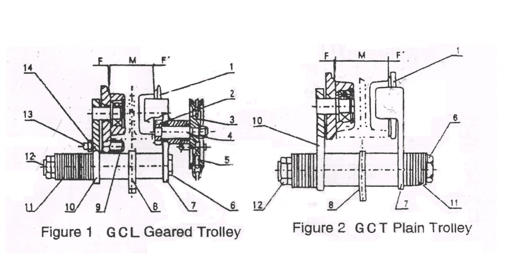
The wheel group design is a key component of the trolley travel, which directly affects the running stability and life. The wheel material is generally ZG340-640 cast steel or 65Mn forged steel, and the tread hardness must reach HB300-380 to reduce wear. The relationship between the wheel diameter D and the wheel pressure P should comply with the standard regulations, and is usually determined by the following formula:
D ≥ cP^(1/3)
Where c is the coefficient, and c=6.3 is taken for the track model P38. The wheel group bearings mostly use spherical roller bearings to compensate for the track installation error. Double-flange wheels can effectively prevent derailment, and single-flange wheels need to be equipped with horizontal guide wheels. The match between the wheel and the shaft generally adopts H7/k6 transition fit to ensure the transmission of torque while facilitating disassembly and maintenance.
The track system includes track selection and installation methods. Common track models include P24, P38, QU70, etc., which are selected according to the wheel pressure. Track installation must ensure: track gauge tolerance ±3mm; horizontality deviation ≤1/1000 track gauge; joint clearance 2-4mm and misalignment ≤1mm. Tracks are usually fixed with pressure plate bolts, which allow for slight adjustments to compensate for thermal deformation. Tracks are usually made of U71Mn high-carbon steel and require quenching to improve wear resistance.
Auxiliary structures include safety facilities such as guardrails, maintenance platforms, and buffers. The height of the guardrail is not less than 1m to prevent people from falling; the width of the maintenance platform is ≥600mm, and the load capacity is ≥2kN/m²; the buffer can be made of polyurethane or rubber to absorb kinetic energy and reduce impact. In addition, a cable pulley or drum device must be designed to provide power to the trolley and keep the line neat.
Structural calculation is a key step to ensure design safety, which mainly includes the following:
Through the above design calculations, it can be ensured that the trolley travel mechanism can meet the use requirements under various working conditions, while taking into account economy and manufacturability. After the structural design is completed, detailed engineering drawings should be output, including assembly drawings, component drawings and part drawings, to provide a basis for subsequent manufacturing.
The power and transmission system of the trolley travel mechanism is the key part of converting electrical energy into mechanical motion. The rationality of its design directly affects the performance, energy consumption and reliability of the whole machine. An optimized transmission system should have the characteristics of high efficiency, low noise, long life and easy maintenance.
As the power source of the travel mechanism, the selection of the motor needs to consider many factors comprehensively. Power calculation is the basis of selection, which is usually determined by the following formula:
P = (W·v)/(6120η)·K
Where W is the total resistance (N), v is the running speed (m/min), η is the transmission efficiency, and K is the safety factor (generally 1.1-1.3). The total resistance W includes friction resistance, ramp resistance (if any) and wind resistance (outdoor crane), among which friction resistance is dominant and can be expressed as:
Wf = β·(Q+G)·(μ·d+2f)/D
β is the inertia coefficient, Q is the rated load, G is the weight of the trolley, μ is the bearing friction coefficient, d is the shaft diameter, f is the rolling friction coefficient, and D is the wheel diameter.
In terms of motor type selection, modern bridge cranes generally use three-phase asynchronous motors, among which the YZR series wound rotor motor is suitable for frequent starting and braking occasions and has good speed regulation performance; the YZ series squirrel cage motor has a simple structure and is easy to maintain, suitable for cranes with lower working levels. For systems requiring precise positioning or variable frequency speed regulation, a variable frequency dedicated motor can be selected. The motor protection level is at least IP54, and the insulation level is F or above to adapt to industrial environments.
The speed selection needs to balance the transmission ratio and efficiency. Generally, a 4-pole or 6-pole motor with a speed of 750-1500r/min is selected to achieve the required output speed through a reducer. The motor is mostly installed in parallel shaft style, fixed on the trolley frame through flange or base, and adjustment gaskets need to be set to facilitate belt or gear meshing adjustment.
The reducer is the core component of the transmission system, which is used to reduce the speed and increase the torque. The calculation formula of the reduction ratio i is:
i = n1/n2 = (π·D·n1)/(v·1000)
n1 is the motor speed (r/min), n2 is the wheel speed (r/min), D is the wheel diameter (mm), and v is the trolley speed (m/min).
The selection of the reducer type needs to consider factors such as transmission power, speed ratio and installation space. Cylindrical gear reducers (such as ZQ type) have high efficiency (η≥96%) and long life, and are suitable for small and medium power; worm gear reducers have large transmission ratio and compact structure, but low efficiency (η=70-80%), and are suitable for intermittent working occasions. In modern design, involute gear reducers are widely used, with low noise and high load-bearing capacity. For large-tonnage cranes, hardened gear reducers can be used to improve life and reliability.
Reducers can be installed in two ways: horizontal and vertical. Horizontal installation is easy to maintain, and vertical installation saves space. The connection between the reducer and the motor and wheel group must ensure coaxiality. Usually, elastic pin couplings or gear couplings are used to compensate for installation errors. Reducer lubrication mostly uses oil pool splash lubrication, and large reducers can be equipped with a circulating lubrication system.
The transmission layout of the trolley travel mechanism mainly includes centralized drive and separate drive. Centralized drive is driven by a motor through a transmission shaft to drive the wheels on both sides at the same time. It has a simple structure and good synchronization, and is suitable for small span (gauge <2.5m) cranes. Separate drive means that the wheels on both sides are driven by independent motors, eliminating the long transmission shaft, with light weight and flexible layout. It is the mainstream choice for modern bridge cranes.
The selection of couplings should consider the requirements of transmitting torque, compensating deviations and buffering vibration reduction. The elastic sleeve pin coupling has a simple structure and low price, which is suitable for small torque transmission; the gear coupling has a high load-bearing capacity and allows large deviations, but requires regular lubrication; the plum blossom-shaped elastic coupling has good buffering performance and is suitable for frequent start-stop occasions. The coupling guard is a necessary safety device to prevent injury from being involved.
The floating shaft design is particularly important in long wheelbase transmission, which can compensate for manufacturing and installation errors and thermal deformation. The floating shaft is usually designed as a smooth shaft with a keyway structure, and the two ends are connected by a coupling. The shaft diameter d can be calculated according to the torsional strength:
d ≥ (9550·P·K/(0.2[τ]·n))^(1/3)
P is the transmitted power (kW), K is the working condition coefficient, [τ] is the allowable shear stress (usually 35-45MPa), and n is the shaft speed (r/min). The shaft material is mostly 45 steel or 40Cr, and the quenching and tempering treatment is used to improve the fatigue strength.
A reliable braking system is the guarantee for the safe operation of the crane. The trolley travel mechanism usually has two sets of braking devices: the service brake is used for normal parking, and the safety brake is used as an emergency backup.
The service brake is mostly an electric hydraulic pusher or an electromagnetic brake, such as the YWZ series hydraulic push rod brake or the TJ2A type electromagnetic brake. The braking torque selection should meet the following requirements:
Mz ≥ Kz·(Q+G)·D/(2i·η)
Kz is the safety factor (≥1.5), i is the transmission ratio, and η is the transmission efficiency. The braking time is usually controlled within 3-5 seconds to avoid load shaking caused by emergency stop.
Safety brakes are usually mechanical, such as ratchet pawls or rail clamps, which automatically operate when power is off or overspeeding. For variable frequency controlled travel mechanisms, electrical braking (regenerative braking + DC braking) can be combined with mechanical braking to achieve smooth parking.
There are two common ways to install the brake: high-speed shaft braking (motor shaft or reducer input shaft) has a small braking torque but a fast response; low-speed shaft braking (wheel shaft) has a large braking torque, but a large inertia and slow response. Modern designs often use high-speed shaft braking, combined with variable frequency speed regulation to achieve precise control.
Through the careful design of the above power and transmission systems, the trolley travel mechanism can be ensured to run smoothly, efficiently and reliably, meeting the use requirements under various working conditions. After the design is completed, the transmission efficiency calculation and thermal balance verification should be carried out to ensure that the system will not fail due to overheating.
The control system of the modern bridge crane trolley travel mechanism has developed from traditional relay control to an intelligent control system with PLC and frequency converter as the core, which greatly improves the operation performance and safety reliability. Excellent control system design can achieve precise speed regulation, smooth start and stop, precise positioning and perfect fault protection function.
The traditional control method uses a cam controller or a resistor speed control system to achieve speed regulation by switching the rotor circuit resistance. This method has a simple structure and low cost, but it has high energy consumption and poor speed regulation performance. It is only suitable for occasions with low working level or limited budget. Resistor speed regulation is usually divided into 3-5 gears, with a speed ratio of about 1:3, large start-brake impact, and limited positioning accuracy.
Modern variable frequency control has become the mainstream solution. The frequency converter using vector control or direct torque control (DTC) technology, combined with encoder feedback to form a closed-loop system, can achieve wide range smooth speed regulation (speed ratio of more than 1:10). Frequency conversion control has the following significant advantages: small starting current (≤1.5Ie), reducing grid impact; high power factor (≥0.95), significant energy saving effect; multiple preset speed modes to adapt to different working conditions; precise torque control to achieve smooth starting and stopping.
The control architecture is usually divided into three layers: the upper layer is the management and monitoring layer, which sets parameters and displays status through the HMI; the middle layer is the control layer, where the PLC processes logic and motion control; the bottom layer is the execution layer, including the inverter, brake, etc. PLC can choose Siemens S7-1200 or Mitsubishi FX series, which has digital and analog I/O, as well as fieldbus communication capabilities. The inverter selection needs to match the motor power and reserve 10-20% margin, such as ABB ACS880 or Siemens G120 series.
Speed regulation is an important function of the control system. There are usually multiple speed modes for the trolley: low speed gear (5-10m/min) is used for precise positioning, medium speed gear (15-20m/min) is for normal operation, and high speed gear (20-30m/min) is used for no-load movement. The inverter parameters need to be optimized: acceleration time 4-8 seconds, deceleration time 5-10 seconds, S curve acceleration and deceleration can effectively prevent load swing.
Positioning control can be achieved in many ways. The simple solution uses a combination of travel switch + deceleration switch to send a signal at a predetermined position to control deceleration and stop, with a positioning accuracy of about ±10mm. High-precision positioning requires the use of an absolute encoder or laser rangefinder, combined with a PLC positioning module, with an accuracy of up to ±1mm. For special applications such as smart warehousing, RFID position identification or visual positioning systems can also be used.
Synchronous control is particularly critical in separate drive systems, and the speed of the motors on both sides must be consistent to prevent the trolley from running off. A master-slave control strategy can be used to take the speed of one side of the motor (master motor) as the follow-up target of the other side (slave motor), and adjust it in real time through the CANopen or Profibus bus. The speed difference between the two wheels fed back by the encoder should be controlled within ±2%, and correction or alarm will be triggered when the difference exceeds the tolerance.
Perfect safety protection is the top priority of control system design. Electrical protection includes: short circuit protection (circuit breaker + fuse); overload protection (thermal relay or electronic protection); undervoltage and phase sequence protection (to prevent reverse operation); emergency stop button (mushroom head type, directly cut off the control power supply). The protection level of all electrical components shall not be lower than IP55, and the grounding resistance of the shell shall be ≤4Ω.
The main operating safety devices are: limit switch (mechanical or proximity type) to limit the travel range of the trolley; overspeed protection (speed switch or encoder detection) to trigger the safety brake; anti-collision system (ultrasonic or infrared sensor) to prevent collision with the end beam or other trolleys. Double limit switch configuration is a common practice: the first stage deceleration, the second stage cuts off the movement and brakes.
Condition monitoring and diagnosis are advanced functions of modern control systems. The sensor network monitors parameters such as motor temperature, vibration, bearing status, brake wear, etc. to predict potential faults. PLC can record operation data (start and stop times, load curve, fault history, etc.), and transmit it to the remote monitoring center via industrial Ethernet to achieve preventive maintenance.
Driver’s cab control is a traditional operation method, which is operated through a linkage table or handle. The linkage table is usually equipped with a master controller (controls the movement of each mechanism), indicator lights, instruments and emergency stop switches. Ergonomic design can reduce operator fatigue, such as seat adjustment, adjustable armrests and foot switches. The driver’s cab should have a good view and the glass windows should meet safety standards (such as tempered glass + guardrails).
Ground remote control is becoming more and more popular, using wireless or wired methods. Wireless remote controllers (such as HBC or Schneider products) usually have: motion control buttons, emergency stop, status indicator lights and power display. The operating frequency is 2.4GHz, the transmission distance is 100-200 meters, and the protection level is IP65. The remote control system must have a “dead” protection function, which automatically stops all mechanisms when the signal is lost.
Automatic operation is an advanced configuration suitable for occasions with fixed processes. Through pre-programmed path planning (such as through teaching or CAD import), the trolley can automatically complete the material collection, transportation and unloading processes. It is necessary to combine barcode/RFID recognition technology to ensure the accuracy of the action. The automation system usually retains the manual operation mode for easy debugging and emergency handling.
Through the careful design of the above control system, the travel mechanism of the bridge crane trolley can achieve efficient, accurate and safe operation, meeting the strict requirements of modern industrial production. After the system design is completed, sufficient FAT (factory testing) should be carried out, including functional testing, safety testing and load testing, to ensure that all performance indicators meet the design requirements.
The safety and maintenance design of the trolley travel mechanism of the bridge crane is a key link to ensure the long-term reliable operation of the equipment and prevent accidents. Excellent safety design not only meets the requirements of regulatory standards, but also actively prevents potential risks; and reasonable maintenance design can significantly improve equipment availability and reduce the cost of the entire life cycle.
The mechanical safety device constitutes the first line of defense for the trolley travel mechanism. As an important energy-absorbing element, the buffer is usually installed to ensure that the trolley travel mechanism always runs smoothly along the predetermined track. In addition, the device also includes an overload protection system. Once an overload operation occurs, it can immediately trigger an alarm and cut off the power supply to avoid mechanical failures and safety hazards caused by overload. At the same time, the design of the trolley travel mechanism also integrates an anti-rollover protection mechanism. Through precise mechanical calculations and structural optimization, it ensures that when a single-side wheel suddenly fails or the track conditions are poor, the equipment can still remain stable to prevent safety accidents caused by tilting.
In order to reduce the difficulty of maintenance and improve the maintainability of equipment, the maintenance design of the trolley travel mechanism of the bridge crane is also ingenious. The modular design concept is widely used, which not only makes the replacement of parts easier and faster, but also greatly reduces the maintenance cost. Key components such as drive units and reducers all use standardized interfaces and can be easily disassembled and assembled without special tools, greatly improving on-site maintenance efficiency. The integration of condition monitoring and fault warning systems enables real-time monitoring of the operating status of the equipment, making it easy to foresee and eliminate potential faults in a timely manner, ensuring the long-term and stable operation of the entire bridge crane system. Polyurethane or rubber materials are used at both ends of the trolley frame, which can effectively absorb collision energy (the absorption rate can reach more than 65%) and reduce impact damage. The anti-derailment device includes horizontal guide wheels and vertical limit wheels, which can prevent the wheels from falling off the track when the track deviates or the wheels wear.
Contact our crane specialists
Send us a message and we will get back to you as soon as possible.