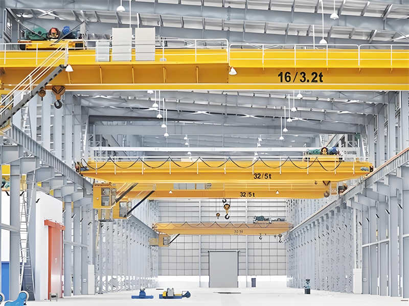
As the core equipment of modern industrial material handling, the QD 16/3.2T electric double-beam bridge crane plays an irreplaceable role in the field of industrial production. This design aims to develop a lifting equipment with high stability and high efficiency. The main lifting capacity is 16 tons and the auxiliary lifting capacity is 3.2 tons. It adopts a box-shaped double-beam structure and combines with an advanced electrical control system to achieve three-dimensional spatial precision handling of materials.
Crane plays a key basic or auxiliary function in the production and transportation of national materials. Its design level is directly related to production efficiency and operation safety. Traditional cranes have problems such as insufficient rigidity and poor stability. This design optimizes the box-shaped main beam structure, improves the operating mechanism, and introduces a new correction technology to increase the lateral rigidity of the equipment by 60%, reduce the height by 20%-30%, and improve the operating efficiency by 40%.
With the rapid development of China’s manufacturing industry, bridge cranes are increasingly used in machine tool loading and unloading, assembly operations, and assembly line fixed-point work, and the performance requirements for cranes are also increasing. This design responds to these needs, integrates multidisciplinary technologies such as mechanical design, metal structure optimization and intelligent control, and is committed to creating a bridge crane that meets the needs of modern industry.
The mechanical design of the QD 16/3.2T electric bridge double-beam crane adopts a modular design concept, dividing the entire system into several functional modules, including metal structure module, lifting mechanism module, operating mechanism module and electrical control module. This modular architecture is not only convenient for design, manufacturing and maintenance, but also can flexibly configure different functions according to user needs.
As the main load-bearing component of the crane, the bridge structure adopts a box-shaped double-girder design, which is composed of two box-shaped main beams and end beams connected by high-strength bolts. The box section is selected based on its excellent bending and torsion resistance. Longitudinal stiffening ribs and transverse partitions are set inside the main beam to effectively improve local stability and overall stiffness. Calculations show that this design increases the lateral rigidity by 60% compared with the traditional single-beam structure. The track is laid on the main beam for the trolley to run. The track adopts QU-type special crane rail and is fixed to the upper flange of the main beam by a pressure plate to ensure the smooth operation of the trolley.
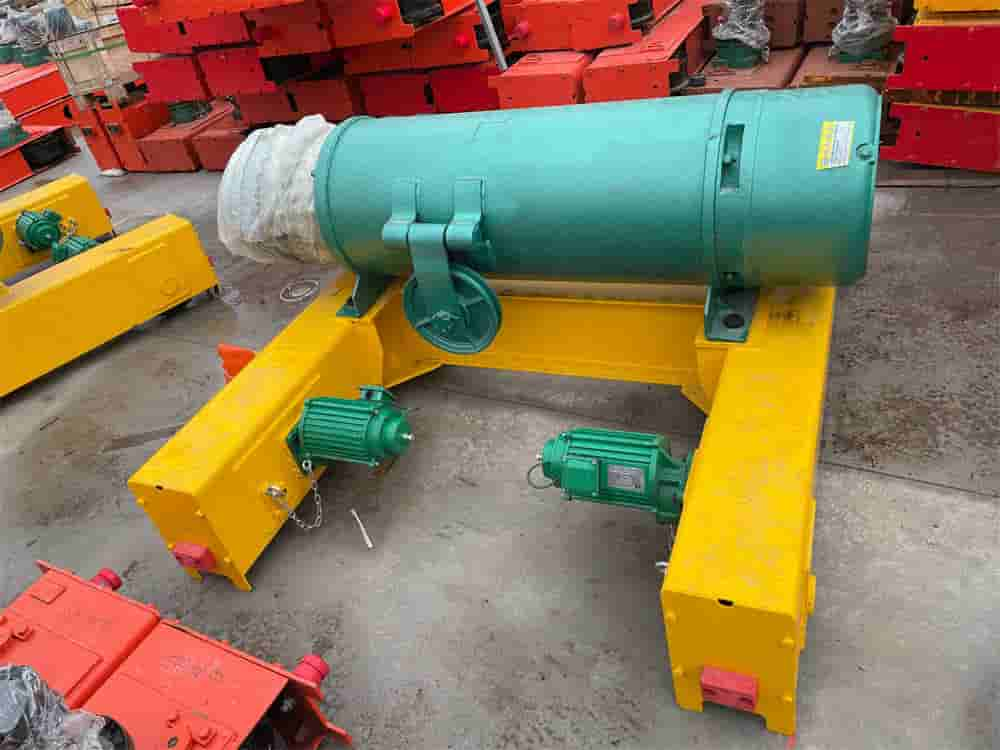
The lifting trolley is the working core of the crane, which includes two major components: the lifting mechanism and the trolley running mechanism. The lifting mechanism is arranged in the middle of the trolley frame, and the complete transmission chain is composed of a motor, a coupling, a brake, a reducer, a drum device and a pulley group. The trolley running mechanism is symmetrically arranged on both sides of the trolley frame, and adopts a “three-in-one” drive device (integrating the motor, reducer and brake into one), which saves space and improves transmission efficiency. The trolley frame adopts a welded steel structure, which consists of end beams, middle cross beams and pulley ledges. It has a compact structure and high strength.
The trolley running mechanism realizes the longitudinal movement of the crane along the factory track. This design adopts a separate drive method, that is, a set of independent drive devices is set on each end beam on both sides. Each set of devices includes components such as motors, brakes, reducers, wheel groups and couplings. The latest technological improvements have introduced a spring-helical rod composite structure and an electric telescopic rod linkage correction device, which has greatly improved the operating stability and track retention ability, and solved the “track gnawing” problem common in traditional cranes.
The hoisting mechanism is the most critical working part of the QD crane, and its design quality directly determines the performance of the whole machine. This design adopts a double drum structure, which serves the main hoisting (16 tons) and auxiliary hoisting (3.2 tons) functions respectively, meeting the lifting needs of users with different load ranges.
The wire rope selection calculation follows ISO standards and crane design specifications, and is determined according to the rated lifting capacity, working level and safety factor. The main hoisting mechanism uses 6×37+FC-φ18mm wire rope with a nominal tensile strength of 1870MPa and a minimum breaking force of 216kN. The safety factor verification formula is n=St/(Q/q)≥[n], where St is the breaking force of the wire rope, Q is the rated lifting capacity, q is the pulley ratio (take 6 times), and [n] is the allowable safety factor (take ≥5.5). After calculation, the actual safety factor n=5.92 meets the requirements of the specification.
The pulley and drum are designed with cast iron material (HT200). The main hoisting pulley group consists of 6 movable pulleys and 6 fixed pulleys to form a balancing system. The pulley diameter D≥20d (d is the diameter of the wire rope), and D=400mm is taken to ensure the bending fatigue life of the wire rope. The drum size is determined according to the number of winding layers (3 layers) and the rope groove parameters. The length is 1800mm and the diameter is 450mm. The involute rope groove transition is used at both ends to reduce the wear of the wire rope^[14][15]. The drum shaft is made of 42CrMo alloy steel, and the fatigue strength is checked after quenching and tempering to ensure sufficient safety margin.
The motor selection is based on the steady-state lifting power calculation, taking into account the lifting speed (main lifting 7.5m/min, auxiliary lifting 12m/min), mechanism efficiency and load combination. The power of the main hoisting motor is P = (Q·v)/(6120η) = (16000×7.5)/(6120×0.85) = 23.1kW. The YZP250M-8 variable frequency motor is selected, with a rated power of 24kW, a standard working mode of S3-40%, and a protection level of IP54, which meets the requirements of heavy-load starting and frequent operation. The motor is equipped with a normally closed brake with a braking torque of not less than 1.5 times the rated torque to ensure that the load can be safely braked when the power is off. The reducer is equipped with a QY3D-400 hardened gear reducer with a transmission ratio of 31.5, an input speed of 720rpm, and an output torque of 18kN·m. The reducer and the motor are connected through a plum blossom elastic coupling to compensate for installation errors and absorb impact vibrations. Calculation of actual lifting speed: vactual = (πDn)/(i·a) = (3.14×0.45×720)/(31.5×6) = 7.2m/min, which is 4% different from the theoretical value and within the allowable range.
The design of the operating mechanism is the core link of the mechanical design of QD crane, which includes the trolley operating mechanism and the trolley operating mechanism. Although the two parts have similar functions, they have significant differences due to different load-bearing characteristics.
The trolley operating mechanism adopts a centralized drive form, with a YZR160L-6 motor (11kW, 953rpm) driving two active wheels through a ZSC-400 reducer (transmission ratio 22.4). The wheel diameter D = 320mm, the tread hardness HB300-380, the bearing uses a spherical roller bearing 22220C, and a certain angular deviation is allowed. The calculation of the trolley running resistance includes the friction resistance Wm=(Q+G)(2f+μd)/D and the slope resistance Wi=(Q+G)α, where Q is the rated load, G is the deadweight, f is the rolling friction coefficient (0.05cm), μ is the bearing friction coefficient (0.02), d is the shaft diameter (90mm), and α is the track slope (taken as 0.001). After calculation, the steady-state operating power is 1.8kW, the starting power after considering the inertia force is 5.4kW, and the motor heating condition meets.
The trolley running mechanism adopts a separate drive design, and each side end beam is equipped with an independent drive unit to avoid the torsional deformation problem caused by the long drive shaft. Each unit uses a YZR180L-8 motor (13kW, 702rpm) with a ZQ-500 reducer (transmission ratio 23.34) to drive two φ630mm wheels^[6][8]. The calculation of the trolley running resistance also needs to consider the wind load (250N/m² for indoor cranes) and the impact of track unevenness. According to the “Crane Design Code” GB/T3811-2008, the non-slip calculation is carried out: the ratio of the active wheel pressure to the total wheel pressure at startup is ≥0.6 to ensure sufficient adhesion.
The design of the braking system is crucial to operational safety. The trolley mechanism uses the YWZ5-315/50 hydraulic push rod brake with a braking torque of 160N·m; the trolley mechanism uses two YWZ6-400/121 brakes, each with a braking torque of 360N·m. The braking time is controlled within a reasonable range (3-4 seconds for the trolley and 6-8 seconds for the trolley) to avoid excessive braking and load swing. The coupling uses an elastic coupling with a brake wheel, the high-speed shaft uses the CLZ type, the low-speed shaft uses the CL type, and the floating shaft design reduces installation stress.
The innovation of the correction device is the highlight of this design. The traditional crane trolley is prone to deflection during operation, resulting in lateral friction between the wheel flange and the track (rail gnawing). This design introduces an electric telescopic rod linkage correction system in the end beam. When the sensors detect that the two sides are not running synchronously, the driving speed of one side is automatically adjusted or the end beam is mechanically pushed and pulled. The correction response time is <0.5 seconds, the accuracy is ±2mm, and the efficiency is improved by 40% compared with the traditional structure.
The metal structure design of the QD 16/3.2T electric bridge crane is based on the box beam, and the structural safety and reliability are ensured through reasonable mechanical models and modern design methods.
The main beam design adopts the form of off-track box beam, with an upper flange width of 1200mm, a lower flange of 1000mm, a web height of 1600mm, and a plate thickness of 6-14mm (depending on the stress distribution). Transverse partitions are set every 1.5m inside the main beam to prevent cross-sectional distortion; longitudinal stiffening ribs are welded on the inner side of the upper and lower flanges to improve local stability. The main beam is calculated as a simply supported beam, with a mid-span bending moment of M=QL/4+GL/8 (Q=16t, G≈12t, L=28.5m). Considering the dynamic load coefficient φ2=1.1 and the impact coefficient φ5=1.05, the maximum bending stress σmax=185MPa<[σ]=230MPa (allowable stress of Q235B steel). The vertical static stiffness of the main beam is controlled within L/800 and the dynamic stiffness is L/1000 to ensure smooth operation. The end beam structure adopts a box-shaped segmented design for easy transportation and on-site assembly.
The cross-sectional dimensions are 800×600mm, the web thickness is 8mm, and the flange thickness is 12mm. The end beam and the main beam are connected by high-strength bolts (10.9 grade M24), and the joint surface is refined to ensure smooth force flow transmission. The end beam has a built-in trolley running mechanism, and the wheel group is fixed by an angular bearing box, allowing ±0.5° deflection. The latest design adds spring-screw rod composite supports at the four corners of the end beam. When the crane is overloaded, it automatically adjusts the force distribution, reduces the local pressure on the track, and increases the wheel life by more than 30%.
The trolley frame is designed as a welded frame structure, consisting of two end beams, two middle cross beams and multiple vertical plates. The material is Q345B low-alloy steel. The pulley ledge is locally strengthened with a thickness of 25mm to withstand the concentrated load of the wire rope. The trolley frame strength analysis uses the finite element method, considering four working conditions: full load lifting, sudden braking, inclined lifting and extreme wind load. The analysis shows that the maximum stress occurs at the pulley support, σmax=210MPa<[σ]=310MPa (Q345B steel), and the safety factor n=1.48. Connection and anti-corrosion design are crucial to structural durability.
The main load-bearing welds are groove welded and ultrasonically inspected after welding; the secondary welds are fillet welded, and the weld leg size is not less than 1.2 times the thickness of the thinner plate. Surface treatment includes sandblasting and rust removal (Sa2.5 level), epoxy zinc-rich primer (80μm) and polyurethane topcoat (60μm), providing more than 10 years of corrosion protection. Key stress areas are regularly inspected (at least once a year) to ensure structural integrity.
The electrical system design of the QD type 16/3.2T electric bridge crane integrates modern control technology and multiple safety protections to achieve efficient, accurate and safe operation of the equipment.
The main circuit design adopts a three-phase AC 380V/50Hz power supply, which is introduced into the crane through a safety busbar or cable drum. The four major mechanisms of main lifting, auxiliary lifting, trolley operation and trolley operation are all controlled by independent circuits, and each circuit is equipped with short-circuit protection, overload protection and pressure loss protection. The motor uses YZR series wound rotor asynchronous motor, which has large starting torque and strong overload capacity, and is suitable for frequent start-stop lifting conditions. The main lifting motor is equipped with a frequency converter to achieve stepless speed regulation and smooth starting and braking, reducing mechanical shock.
The control system provides two operating modes: cab control and ground remote control. There is a linkage control console in the cab, and the operating handle has zero-position self-locking and emergency stop functions; the remote control system uses 2.4GHz wireless technology, with a control distance of up to 150m, and has signal encryption and anti-interference capabilities. PLC is the control core, which monitors the status of each mechanism in real time, processes operating instructions and executes safety interlocks. Important signals (such as limit, overload, etc.) are directly connected to the control circuit using hard wires to ensure that the machine can be shut down for protection even if the PLC fails.
The safety protection device constitutes a multi-layer protection barrier:
The electrical cabinet is designed to meet the IP54 protection level. The main components include circuit breakers, contactors, overcurrent relays, PLCs and inverters. An air conditioner is installed in the cabinet to maintain the temperature within the range of 0-40℃ to ensure stable operation of electronic equipment. All cables are flame retardant, and the mobile cables on the bridge are protected by C-type rails to avoid mechanical damage.
The manufacturing process of the QD 16/3.2T electric bridge crane integrates modern welding technology, precision machining and intelligent assembly methods to ensure the consistency and reliability of product quality.
The cutting and forming process uses a CNC plasma/flame cutting machine to cut steel plates, and the cutting tolerance is controlled within ±1mm. The camber pre-bending of the upper and lower flanges of the main beam is completed by a large hydraulic press, and the pre-camber value is set according to L/1000 (L is the span) to compensate for the deflection after loading. When assembling the box beam, a special clamp is used to ensure the relative position of each plate, focusing on controlling the verticality of the web (≤h/500, h is the beam height) and the parallelism of the flange plate (≤2mm/m). The main welds are made by submerged arc automatic welding, preheating 100-150℃ before welding, interlayer temperature control, and insulation and slow cooling after welding to reduce residual stress.
Machining is mainly concentrated on key parts such as wheel axle holes, coupling joint surfaces and reducer mounting seats. The wheel axle holes are machined by boring machines with a roundness error of ≤0.02mm and a surface roughness of Ra1.6; the reducer mounting surface is milled and then ground with a flatness of 0.1mm/m. All machined surfaces are coated with anti-rust oil before assembly, and the threaded connections are tightened with a torque wrench according to the predetermined torque (such as the final tightening torque of M24 high-strength bolts is 620N·m).
The assembly process follows the principle of “components first, then the whole”: first complete the assembly and test run of the trolley, then assemble the bridge structure, and finally hoist the trolley onto the track. The trolley running mechanism is debugged after the end beam is in place, and the vertical deflection (≤l/400, l is the measurement length) and horizontal deflection (≤l/1000) of the wheel are measured, and the contact points of each wheel are adjusted to form a horizontal plane. After the structure is assembled, key dimensions such as the main beam camber (0.9-1.4L/1000), diagonal difference (≤5mm) and trolley gauge difference (±2mm) are checked.
The debugging and testing are divided into three stages: no-load test, static load test and dynamic load test. The no-load test checks the operating status of each mechanism and the response of the control system; the static load test gradually loads to 1.25 times the rated load to measure the main beam deflection (≤L/700) and structural integrity; the dynamic load test performs various combined actions at 1.1 times the rated load to verify the braking performance, noise level and mechanism coordination. Finally, a continuous operation test (at least 3 working cycles) is carried out to check whether parameters such as temperature rise and vibration are normal.
This QD type 16/3.2T electric bridge double-beam crane mechanical design project has developed a lifting equipment with superior performance, safety and reliability through systematic design calculation, structural optimization and technological innovation. The design process strictly follows national standards and industry specifications, and comprehensively applies modern design methods and advanced manufacturing technologies, so that the product has reached the industry-leading level in terms of load-bearing capacity, operational stability and ease of operation^[1][4][7].
The main technical innovations are reflected in three aspects:
Economic and social benefit analysis shows that the crane designed and manufactured by this design saves 15-20% energy compared with similar products, reduces maintenance costs by 30%, and extends its service life to more than 25 years. Its widespread application will improve material handling efficiency, reduce energy consumption, and have positive significance for promoting industrial green development and safe production.
Future research can further explore the deep integration of intelligent technology (such as automatic positioning, anti-sway control) and cranes, as well as the application of new composite materials in metal structures, to continuously improve crane performance and user experience.
Contact our crane specialists
Send us a message and we will get back to you as soon as possible.