As the core equipment for modern industrial material handling, bridge cranes play an irreplaceable role in factories, warehouses, material yards and other occasions. The 10-ton bridge crane designed this time aims to achieve the goal of minimizing costs, rationalizing layout and modernizing functions through optimized design, in view of the current situation of relatively backward domestic crane technology and aging equipment. Many bridge cranes currently used in my country are still copied based on backward foreign technology. Some equipment is even products from the 1970s and 1980s, which are difficult to meet the needs of modern industry in terms of quality and function. This design will combine modern design concepts and computer-aided technology to develop a 10-ton bridge crane with stable performance and high work efficiency.
The bridge crane is mainly composed of a bridge structure, a lifting mechanism, a running mechanism and an electrical control system. It can operate in a rectangular site and above it, making full use of the spatial position without being hindered by ground equipment. This design will fully consider the coordination and optimization of these key components to ensure that the crane can operate safely and reliably under various working conditions. Compared with traditional cranes, this design pays special attention to the introduction of innovative design elements and the application of computer-aided design methods, striving to improve design efficiency while ensuring performance.
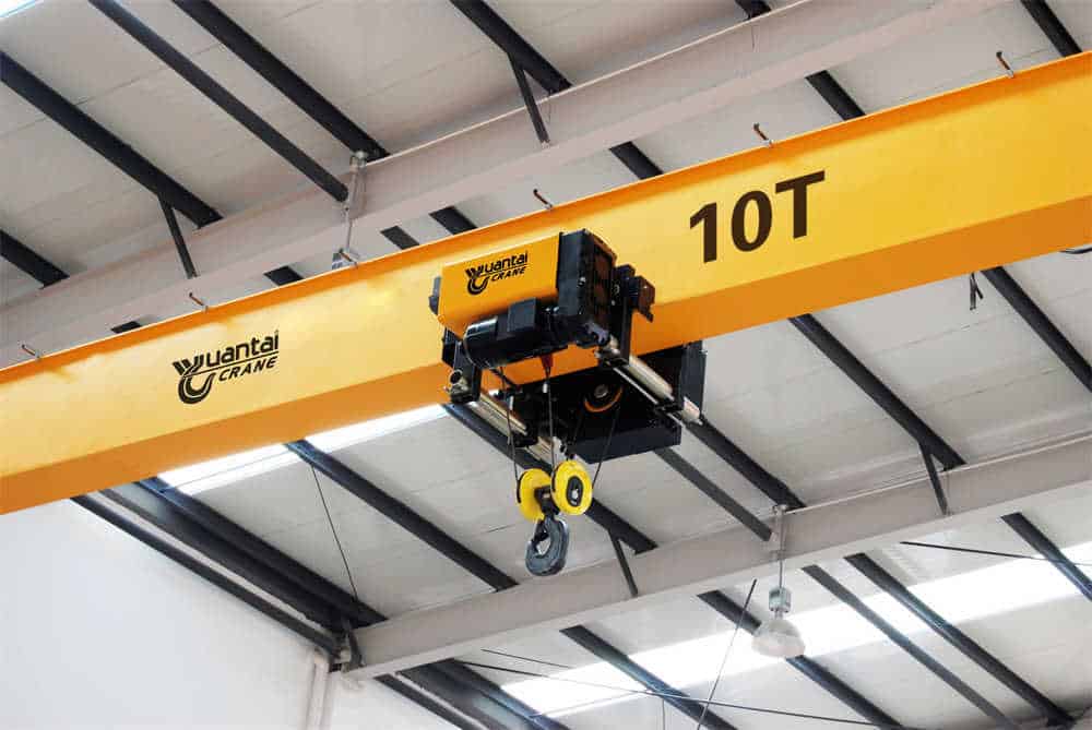
Based on the actual needs of industrial production and comparative analysis of multiple references, the main technical parameters of this 10-ton bridge crane are determined as follows:
Basic parameters:
Speed parameters:
Structural parameters:
The establishment of these parameters refers to the data of graduation design and engineering practice of many universities, which not only ensures the safety and reliability of the equipment, but also takes into account the economy and practicality. In particular, the working level is selected as A5, which is suitable for medium-frequency use occasions in places such as machining workshops, assembly workshops and warehouses, and can meet the material handling needs of most industrial enterprises. The setting of speed parameters strikes a balance between production efficiency and operation accuracy, avoiding excessive load swing due to excessive speed, affecting positioning accuracy and operation safety.
The overall structural design of the bridge crane is the core of the project, which requires comprehensive consideration of many factors such as force characteristics, material selection, manufacturing process and cost control. This design adopts a box-shaped double-beam bridge structure, which is composed of two box-shaped main beams and two transverse end beams. The double-beam bridge frame runs on the bridge frame, which can lift and horizontally transport various objects. This structural form has the characteristics of high rigidity, high strength and good stability, and is particularly suitable for the working conditions of 10-ton cranes.
As the main load-bearing structure of the crane, the design quality of the bridge frame directly affects the performance and service life of the whole machine. The bridge frame of this design adopts a regular box-shaped double-beam layout, which is mainly composed of main beams, end beams, walkways and railings.
Main beam design:
End beam design:
Dynamic stiffness issues are specially considered in the bridge design. The cross-sectional dimensions of the main beam are optimized through finite element analysis to ensure that the static deflection at the mid-span under rated load does not exceed L/700, and does not exceed L/500 under dynamic load, ensuring running stability and positioning accuracy. At the same time, the bridge adopts a modular design concept, which is convenient for manufacturing, transportation and on-site installation, reducing the overall cost.
The main beam is the most important load-bearing component of the bridge crane, and its design calculation must comply with relevant standards such as GB/T3811-2008 “Crane Design Specifications”. The main beam of this design adopts a skewed box beam structure, and the track is arranged on the side of the upper flange of the main beam, rather than the center.
Main beam stress analysis:
Key points of strength calculation:
Key points of stiffness calculation:
The main beam manufacturing process adopts segmented welding method, each segment is about 6-8 meters long, which is convenient for transportation and on-site assembly. The welding joint adopts K-type groove to ensure full penetration. After welding, the whole annealing treatment is required to eliminate welding stress, and non-destructive testing (UT+RT) is performed to ensure the quality of the weld. The camber is achieved by prefabricated curve cutting, avoiding the use of forced deformation methods such as flame correction.
As an important part of the bridge frame, the end beam is responsible for transferring loads, connecting the main beam and installing the trolley running mechanism. This design adopts a separated end beam structure, and each end beam is connected to the end of the main beam through high-strength bolts.
Key features of the end beam:
Key points of connection design:
The correction mechanism is specially considered in the design of the end beam. By adjusting the wheel tread taper or using eccentric sleeves, the occurrence of the crane “biting the rail” phenomenon is prevented. At the same time, horizontal guide wheels are set on the end beam, which are mandatory when the crane span is ≥16.5m to reduce the impact of horizontal lateral forces generated during operation.
The mechanism design of the bridge crane directly affects the working performance and reliability of the equipment. This 10-ton bridge crane mainly includes three major mechanisms: lifting mechanism, trolley running mechanism and trolley running mechanism. Each mechanism needs to be independently designed and calculated according to the working characteristics, while considering the coordination and cooperation between each other.
The lifting mechanism is the core component of the crane, responsible for the vertical lifting and lowering of the load. This design adopts a single drum and single motor drive solution, and is equipped with a double braking system to ensure safety.
Main components:
Main points for calculation of lifting mechanism:
The lifting mechanism is arranged on the trolley frame, adopts parallel shaft transmission, and has a compact structure. In order to adapt to different working conditions, the lifting mechanism is equipped with a variable frequency speed regulation system with a speed adjustment range of 1:10, which can achieve precise positioning (±5mm). At the same time, multiple safety protection devices are set, including the upper limit position limiter, overload limiter and emergency power-off device.
The trolley running mechanism realizes the horizontal movement of the hoisted object along the main beam direction. This design adopts a centralized drive mode, and the wheels on both sides are synchronized through the transmission shaft.
Composition of the trolley running mechanism:
Key points of trolley operation calculation:
The trolley frame adopts a steel plate welded structure with an inspection platform and guardrails. The wheel layout adopts a four-corner eight-wheel form (balance beam structure), which can ensure safe operation even if one wheel on one side fails. The trolley track uses QU70 crane special rails, which are fixed to the upper flange of the main beam through a pressure plate, and the joints are polished and smooth to ensure the smooth passage of the trolley.
The trolley running mechanism drives the entire crane to move longitudinally along the factory track. This design adopts a four-corner drive mode (all-wheel drive), and the two wheels on each end beam are active wheels.
Composition of trolley running mechanism:
Main points of trolley operation calculation:
The trolley running mechanism adopts an independent drive unit design. Each drive unit includes a motor, brake, reducer and wheel set, which is easy to maintain and replace. Considering the “three-legged” phenomenon that may occur in a span of 22.5m, the compensation capacity of the flexible fulcrum is specially strengthened during the design, and the load of each wheel set is automatically adjusted through the articulated balance beam structure. At the same time, the trolley running mechanism is equipped with a correction system, which automatically alarms and adjusts when the two sides are out of sync by more than 200mm to prevent damage to the bridge frame.
The electrical control system of modern bridge cranes is not only related to the basic operating functions of the equipment, but also directly affects the operating performance, energy efficiency level and safety and reliability. This 10-ton bridge crane adopts a full frequency conversion speed control system to achieve smooth start-up, precise speed regulation and reliable braking of each mechanism.
The main circuit provides power for the motors of each mechanism and is equipped with complete protection functions.
Main circuit configuration:
Circuit features:
The control system adopts PLC + touch screen architecture to achieve intelligent operation and status monitoring.
Control function module:
Key safety devices:
The selection of electrical components follows the principle of reliability first, and mainly uses Schneider, Siemens and other brand products.
List of main components:
Electrical layout:
Special attention is paid to electromagnetic compatibility (EMC) design in the control system design. All cables are shielded cables, and reactors are installed on the inverter output to effectively suppress high-frequency interference. At the same time, the system reserves an Internet of Things interface, which can be connected to the factory equipment management system to achieve remote monitoring and preventive maintenance.
The safety performance of bridge cranes is directly related to the safety of operators and equipment. At the same time, humanized design can significantly improve the use efficiency and operating comfort. The design of this 10-ton bridge crane strictly follows the standards and specifications such as GB6067-2010 “Safety Regulations for Hoisting Machinery” to build a multi-level safety protection system.
Mechanical safety is the basis of crane safety, and intrinsic safety is achieved through structural design and safety devices.
Structural safety measures:
Key safety components:
The electrical safety system ensures that the crane can be safely shut down under various abnormal conditions.
Electrical safety measures:
Undervoltage protection: when the voltage of the crane power supply drops to the preset critical value, the undervoltage protection device will respond immediately, by cutting off the contactor or relay coil circuit, etc., to prevent the equipment from being unstable or even shutting down due to insufficient voltage, and at the same time avoid the reduction or damage of the life of electrical components due to low voltage operation.
Contact our crane specialists
Send us a message and we will get back to you as soon as possible.