This design scheme is a systematic design for 32/5t double-girder bridge cranes, covering the core parts such as main and auxiliary lifting mechanisms, trolley running mechanisms, bridge structures and trolley running mechanisms. As a key equipment for modern industrial material handling, double-girder bridge cranes play an irreplaceable role in factories, warehouses, power stations and other places. This design will follow the relevant national standards and specifications, combined with the latest technological developments, to provide a complete set of design schemes, including parameter calculation, component selection, structural analysis and safety measures to ensure that the crane operates safely and reliably under working level M5 conditions, while taking into account economy and maintenance convenience.
The 32/5t double-girder bridge crane is a typical heavy-duty industrial lifting equipment, consisting of a bridge, a trolley running mechanism, a trolley and electrical equipment. It can operate in a rectangular site and above it to achieve vertical lifting and horizontal handling of materials. This design adopts a main and auxiliary hook configuration, with a rated lifting capacity of 32 tons for the main hook and 5 tons for the auxiliary hook, to meet the lifting needs of materials of different weights.
Basic technical parameters:
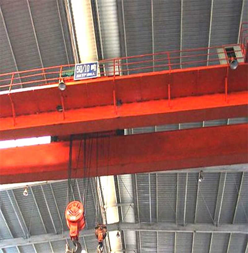
Table: Main technical parameters of 32/5t double beam bridge crane
| Parameter name | Main hook parameters | Auxiliary hook parameters | Overall parameters |
| Rated lifting capacity | 32t | 5t | – |
| Lifting height | 16m | 18m | – |
| Lifting speed | 7.5m/min | 19.7m/min | – |
| Work Level | M5 | M5 | M5 |
| Motor power | 42KW(YZR280S-10) | 17KW(YZR180L-6) | – |
| Span | – | – | 22.5m(Adjustable) |
The standards and specifications followed in the design include: “Regulations on Safety Supervision of Special Equipment”, “Safety Regulations for Hoisting Machinery” (GB6067.1-2010), “Design Specifications for Cranes” (GB/T3811-2008), etc. The design of the metal structure of the crane adopts the allowable stress method to ensure sufficient strength, rigidity and stability under the rated load and various dynamic loads. The selection of all mechanical components should comply with relevant industry standards, and the electrical equipment must have the necessary protection level and safety protection devices.
The crane bridge adopts a skewed box-shaped double-beam structure, which has the advantages of high rigidity, light weight and mature manufacturing technology. The main beam and the end beam are connected with high-strength bolts for easy transportation and on-site installation. The trolley adopts a double-track double-wheel structure with a track gauge of 2500mm and a wheelbase of 2800mm, with a reference deadweight of about 11.5t. The trolley running mechanism adopts a separate drive mode to ensure smooth and synchronous operation.
The main and auxiliary lifting mechanism are the core working mechanisms of 32/5t double-beam bridge cranes. The rationality of their design is directly related to the performance and safety and reliability of the whole machine. The main lifting mechanism is responsible for the lifting and lowering of 32 tons of weight, and the auxiliary lifting mechanism is used for the rapid lifting of materials below 5 tons. The coordinated work of the two can significantly improve the operating efficiency and flexibility of the crane.
The main lifting mechanism adopts a pulley block-wire rope transmission system. The transmission scheme is designed as the motor transmits power to the reducer through the coupling, and the output shaft of the reducer drives the drum to rotate, and drives the hook to rise and fall through the wire rope and pulley block. Considering the lifting capacity of 32 tons, the pulley block adopts a double-linked structure, and the ratio is determined to be 6 according to calculation to ensure that the wire rope will not move abnormally when lifting goods.
Motor selection calculation:
According to the lifting capacity, lifting speed and pulley block ratio, it is calculated that the power demand of the main lifting mechanism motor is about 42kW. The YZR280S-10 wound rotor asynchronous motor is selected, with a rated power of 42kW and a speed of 571r/min. This type of motor has the characteristics of large starting torque and strong overload capacity, which is very suitable for the periodic start-stop working mode of the crane.
Wire rope selection calculation:
The wire rope is the key load-bearing component of the lifting mechanism, and its selection directly affects the safety of the mechanism. According to the rated lifting weight, pulley block ratio and safety factor requirements, the main lifting mechanism uses 6×37+FC-φ22mm wire rope with a nominal tensile strength of 1870MPa and a minimum breaking force of 298kN. The safety factor verification meets the requirement of n≥6 to ensure sufficient safety margin under the maximum working load.
Drum design:
The drum is cast and processed with QT600-3 ductile iron, and the diameter is determined to be φ800mm based on the wire rope diameter and bending fatigue life. The following factors are considered in the calculation of drum length: lifting height 16m, pulley ratio 6, wire rope diameter 22mm, and 3 safety circles. According to calculations, the effective rope length of the drum is about 2000mm, the total length is 2500mm, the wall thickness is 40mm, and the strength is checked to ensure that no plastic deformation occurs under the maximum rope tension.
Braking system:
The main lifting mechanism is equipped with a YWZ-400/90 hydraulic push rod brake with a braking torque of 1600N·m to ensure reliable braking in power failure or emergency situations. The brake is installed on the high-speed shaft, the response time is ≤0.2s, and the braking deceleration is controlled within the range of 0.2-0.4m/s² to avoid load shaking caused by sudden braking.
Reducer selection:
According to the transmission ratio and output torque requirements, the ZQ500-III-3CA reducer is selected, with a transmission ratio of 31.5, an input speed that matches the motor, and an output torque that meets the maximum lifting load requirements. The reducer adopts three-stage gear transmission, the gear material is 20CrMnTi, and after carburizing and quenching treatment, the tooth surface hardness is HRC58-62, ensuring sufficient contact fatigue strength and bending fatigue strength.
The design principle of the auxiliary lifting mechanism is similar to that of the main lifting mechanism, but due to the small lifting weight (5t) and high lifting speed (19.7m/min), there are some differences in parameter selection. The auxiliary lifting mechanism pulley group ratio is selected as 2, and the balance pulley is arranged in the middle of the pulley group to prevent excessive deflection of the wire rope.
The auxiliary lifting mechanism uses the YZR180L-6 motor with a power of 17kW and a speed of 955r/min, which is more suitable for high-speed lifting needs. The reducer uses the ZSC-600-IV-1 type with a transmission ratio of 24.6, which matches the motor and drum well. The brake uses a braking torque of 630N·m to ensure that the 5t load can be safely braked.
Coupling selection:
The high-speed shafts of the main and auxiliary lifting mechanisms use gear couplings to connect the motor and the reducer, and a compensation shaft is set in the middle to allow a certain installation error. The low-speed shaft uses a CLZ-type gear coupling to connect the reducer and the drum, which allows small radial and angular deviations while transmitting large torque.
Safety device configuration:
The main and auxiliary lifting mechanisms are equipped with multiple safety protection devices, including the upper limit position limiter, overload limiter, electrical overcurrent protection, etc. The main lifting mechanism is also equipped with a heavy hammer height limiter, which automatically cuts off the lifting power when the hoist reaches the upper limit position to avoid over-hoisting accidents. All safety devices meet the requirements of GB6067.1 to ensure that the crane can be shut down in time under abnormal conditions.
Table: Comparison of main components of main and auxiliary lifting mechanisms
| Part Name | Main lifting mechanism parameters | Auxiliary lifting mechanism parameters | Remark |
| Electric Motor | YZR280S-10,42KW,571r/min | YZR180L-6,17KW,955r/min | Wound rotor motor |
| Reducer | ZQ500-III-3CA,i=31.5 | ZSC-600-IV-1,i=24.6 | Gear Drive |
| Brakes | YWZ-400/90,1600N·m | YWZ-200/25,630N·m | Hydraulic push rod |
| Wire Rope | 6×37+FC-φ22mm | 6×37+FC-φ14mm | 1870MPa |
| Pulley ratio | 6 | 2 | Double structure |
| Roll size | φ800×2500mm | φ500×1800mm | Ductile Iron |
The control system of the main and auxiliary lifting mechanisms adopts an independent drive mode. The main and auxiliary hooks can be operated separately or work together. The main lifting mechanism considers using variable frequency speed control to achieve stepless speed regulation of 0.7-7.5m/min, which is convenient for precise positioning and slow lifting of large items. The protection level of all electrical components is not less than IP54, which is suitable for dust and humidity conditions in industrial environments.
The trolley running mechanism is a key component that drives the crane trolley to move horizontally along the main beam track. Its design quality directly affects the positioning accuracy and running stability of the crane. The trolley of the 32/5t double-beam bridge crane carries the main and auxiliary lifting mechanisms and runs on them. It needs to overcome the wheel pressure generated by the lifting load and the weight of the trolley to ensure stable operation under various working conditions.
The trolley running mechanism adopts a centralized drive mode. The motor is connected to the transmission shaft through a vertical reducer, and then the power is distributed to the wheel groups on both sides through a coupling. This transmission method ensures that the wheels on both sides run synchronously to avoid deflection during the operation of the trolley. The layout of the transmission system fully considers the space limitations on the trolley frame to ensure that each component is compactly installed and easy to maintain.
The drive motor uses a YZR series wound rotor asynchronous motor. According to the calculation, the power is selected to be 5.5kW and the speed is 940r/min. The motor has good starting performance and overload capacity, which is suitable for the working characteristics of the crane’s frequent start and stop. The motor is connected to the brake wheel through an elastic pin coupling, and then connected to the reducer input shaft through a gear coupling. This arrangement is convenient for installation, adjustment and daily maintenance.
The reducer uses a vertical sleeve reducer with a transmission ratio of about 16. The output shaft is directly mounted on the trolley’s active wheel axle, which has a compact structure and is easy to install. The reducer gear adopts a hard tooth surface grinding process with a precision level of 7, ensuring smooth transmission, low noise and high efficiency. The reducer is lubricated with oil immersion lubrication, equipped with an oil level indicator and an oil drain plug for easy inspection and maintenance.
The trolley adopts a four-wheel support structure, two of which are active wheels and two are driven wheels. The wheel material is ZG340-640 cast steel. After quenching, the tread hardness reaches HB300-380, and the wheel rim hardness is appropriately reduced to prevent brittle fracture. The wheel diameter is determined to be φ500mm based on the wheel pressure calculation, and the road width is 120mm, matching the QU70 crane special track.
Wheel pressure calculation is a key link in trolley design. The maximum wheel pressure occurs when the main hook is fully loaded and the trolley is at the limit position. The maximum wheel pressure is calculated to be about 22t; the minimum wheel pressure occurs in the unloaded state, ensuring that the trolley will not slip under any working conditions. The wheel bearing uses a spherical roller bearing, which can automatically compensate for the slight deformation of the trolley frame and extend the service life.
The track installation adopts a pressure plate fixing method. The track has good contact with the upper flange of the main beam, and the joint has a smooth transition. The gauge tolerance is controlled within ±3mm to ensure that the trolley runs smoothly without impact. Car stops and buffer devices are set at both ends of the track to prevent the trolley from accidentally derailing or hitting the end beam to cause an accident.
The trolley running mechanism is equipped with a hydraulic push rod brake. The braking torque is calculated and determined according to the maximum braking distance requirements. The YWZ-200/25 type brake is selected with a braking torque of 315N·m. The brake is installed on the brake wheel at the tail of the motor, which responds quickly and brakes smoothly, ensuring that the trolley can stop accurately within the specified distance.
The trolley operating mechanism is equipped with multiple safety protection devices, including travel limit switches, buffer springs, and anti-derail protection. The travel limit switches are installed at both ends of the frame. When the trolley approaches the end of the track, it automatically cuts off the power supply of the running motor to prevent it from hitting the end beam. The buffer device uses a polyurethane buffer to absorb collision energy and reduce impact.
The trolley running speed is designed to be 45m/min, and smooth starting and braking are achieved through frequency conversion control to avoid load shaking. The operating mechanism adopts a three-in-one drive device (motor, brake, and reducer integrated) to simplify the installation process, improve transmission efficiency, and reduce maintenance workload. The trolley frame adopts a box beam structure with sufficient strength and rigidity to withstand the lifting load and the dynamic load during the operation of the trolley.
The trolley frame is the basic structure supporting the lifting mechanism and the trolley running mechanism. It adopts a steel plate welded box structure. The main beam and end beam are both box-shaped sections, which have the characteristics of high torsional rigidity and good stability. The height of the trolley frame main beam is about 800mm, the width is about 600mm, and the plate thickness is determined according to the load calculation, generally 12-20mm.
The design of the trolley frame considers the following load combinations: lifting load (considering the dynamic load coefficient ψ₂=1.1), the weight of the trolley, the running inertia force, the lateral force of the deflected operation, etc. The strength and stiffness of the trolley frame under the most unfavorable load conditions are verified by finite element analysis. The maximum stress does not exceed the allowable stress of the material, and the maximum deflection does not exceed 1/1000 of the span.
Necessary maintenance platforms and railings are set on the trolley frame to facilitate the maintenance of the lifting mechanism and the running mechanism. The platform is made of anti-slip steel plate, and the height of the railing is not less than 1050mm, which meets the requirements of safety regulations. The connection between the trolley frame and the end beam is connected with high-strength bolts to ensure the integrity of the structure and facilitate on-site installation and disassembly.
The trolley weighs about 11.5t. During the design, the weight is reduced by optimizing the structure while ensuring strength and rigidity, and the wheel pressure load of the main beam is reduced. The surface of the trolley frame is sandblasted to remove rust and sprayed with protective paint to ensure good anti-corrosion performance in industrial environments and extend service life.
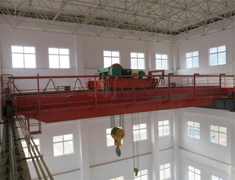
The bridge is the main structure of the double-beam bridge crane, which bears the important functions of bearing all loads, providing running tracks and maintaining the stability of the whole machine. The bridge design of the 32/5t double-beam bridge crane adopts a skewed box-shaped double-beam structure, which consists of two main beams, two end beams, walkways and guardrails. It has the characteristics of compact structure, light weight and high rigidity.
The main beam is the most critical load-bearing component in the bridge structure. This design adopts a skewed box-shaped beam structure, that is, the track is not on the center line of the beam, but biased to one side of the main web. This structural form increases the torsional rigidity of the main beam, reduces the torsion of the beam body caused by the wheel pressure of the trolley, and is convenient for arranging walkways and conductive slide wires. The cross-sectional height of the main beam is determined to be about 1600mm according to the span calculation, and the width is 600mm, which meets the strength and rigidity requirements.
The upper and lower flange plates of the main beam are made of Q345B steel plates with a thickness of 16-24mm and a web thickness of 10-14mm. Different plate thicknesses are used in the mid-span and end according to the distribution of bending moment and shear force to achieve reasonable use of materials. Longitudinal stiffening ribs and transverse large partitions are set inside the main beam with a spacing of about 1.5m to enhance the local stability of the web and prevent excessive local stress under concentrated wheel pressure.
The main beam design considers the following load combinations: deadweight load, trolley and lifting load (considering the dynamic load coefficient ψ₂=1.1), trolley running inertia force, lateral force of skew operation and wind load (calculated according to the maximum wind pressure of 250Pa in the working state). The allowable stress method is used to calculate the strength of the main beam to verify the bending normal stress, shear stress and composite stress of the mid-span section and the support section to ensure that the maximum stress does not exceed the allowable stress of the material under various working conditions.
The stiffness verification of the main beam is equally important. When the rated load is located in the middle of the span, the vertical static deflection of the main beam does not exceed 1/800 of the span (about 28mm for a span of 22.5m). The horizontal stiffness of the main beam also needs to be verified to control the horizontal displacement within a reasonable range to ensure that there is no obvious deflection and track jamming when the trolley is running.
The end beam is a key component that connects the two main beams and supports the trolley running mechanism. It also adopts a box-shaped section structure, with a height matching the main beam and a width of about 500mm. The design of the end beam needs to consider the support reaction force transmitted by the main beam and various dynamic loads during the trolley operation, especially the horizontal inertia force generated when the trolley starts and brakes.
The connection between the end beam and the main beam is connected by high-strength bolts, and the positioning pins are used to ensure the installation accuracy. The connection node is designed as a rigid node, which can effectively transmit bending moment and shear force and maintain the overall shape of the bridge. The trolley buffer and car stop are set on the end beam to absorb the collision energy when the crane runs to the end of the track to protect the crane structure and the plant support structure.
Double-rim wheel sets are installed at both ends of the end beam, with a wheel diameter of φ700mm, matching the QU80 track. Reinforced ribs are set inside the end beam to improve the local strength of the wheel support and prevent excessive local stress under the maximum wheel pressure. The trolley drive device, including motors, reducers and brakes, is also installed on the end beam.
The walkway is an important auxiliary structure on the bridge frame, arranged on the outside of the main beam to provide a passage for inspection and maintenance. The width of the walkway is not less than 600mm, made of anti-slip steel plates, and guardrails are set on both sides to ensure the safety of workers during walking. The design of the walkway fully considers the bearing capacity and durability, and can withstand various complex inspection operations and long-term wear and tear. Its structure usually includes crossbeams, longitudinal beams and stiffening plates connecting the two to form a solid and stable walking plane.
The auxiliary structure refers to a series of facilities matching the walkway, such as escalators, elevators, safety stairs, etc. These facilities are set according to actual needs to provide all-round, convenient and safe inspection and maintenance conditions. Escalators and elevators usually connect the main bridge and the platform to facilitate the workers to go up and down; the safety stairs are emergency passages set up under or on the side of the platform to ensure that people can quickly evacuate to a safe area in an emergency.
These auxiliary structures are also designed with practicality and durability in mind to ensure that they can maintain their functionality and safety in harsh environments. At the same time, they also greatly improve the overall efficiency and comfort of the bridge, providing workers with a comfortable and safe inspection and maintenance environment.
Contact our crane specialists
Send us a message and we will get back to you as soon as possible.