This report comprehensively introduces the design principle, structural characteristics, technical parameters and application scenarios of 50t/10t double-beam mid-rail box-type bridge crane. As a large-tonnage, high-efficiency industrial lifting equipment, this type of crane plays a vital role in the heavy industry field. The report will start with the basic concept of the crane, analyze its structural composition, design points, operating principles and safety configuration in detail, and discuss the selection considerations under different application scenarios. By systematically sorting out the technical parameters and performance characteristics, this report aims to provide a comprehensive reference basis for engineering and technical personnel, and at the same time help companies understand how to correctly select and optimize the use of such heavy lifting equipment to meet various heavy material handling needs.
The 50t/10t double-beam mid-rail box-type bridge crane is a typical representative of bridge cranes. The “50t/10t” in its name means that the crane is equipped with two main and auxiliary lifting mechanisms. The rated lifting capacity of the main lifting is 50 tons and the rated lifting capacity of the auxiliary lifting is 10 tons. This double hook configuration greatly expands the operating flexibility of the crane. “Double beam” means that the crane bridge is composed of two main beams, which provides higher stability and load-bearing capacity compared with the single beam structure. “Mid-track” indicates that the crane track layout is that the track is placed on the center line of the main beam, which is different from the off-track layout. “Box-type” means that the main beam adopts a box-shaped structure. This closed cross-section form gives the main beam excellent bending and torsion resistance.
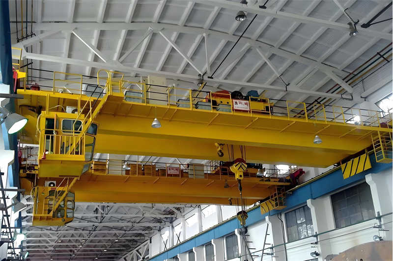
From the basic structure, the 50t/10t double-beam mid-track box-type bridge crane consists of three main parts: bridge, trolley running mechanism and lifting trolley. The bridge, as the skeleton of the entire crane, is composed of two box-shaped main beams and two transverse end beams connected or welded by high-strength bolts to form a rigid spatial structure. The main beam bears the entire load weight and transfers it to the end beam and the supporting track. The box-shaped structure is usually equipped with partitions to enhance local stability. The end beam not only connects the two main beams, but also installs the drive device and driven wheel set of the trolley running mechanism to ensure that the crane can move longitudinally along the factory track. The platform is set on one side of the main beam, which is used to install the trolley travel mechanism and the auxiliary slide line for powering the trolley electrical equipment. The other side is equipped with a maintenance passage protected by guardrails.
The lifting trolley is the core component for completing the lifting and lateral movement of materials. The 50t/10t trolley consists of three parts: the main lifting mechanism (50t), the auxiliary lifting mechanism (10t) and the trolley running mechanism. The trolley frame adopts a welded steel structure, on which the motor, reducer, drum, brake and pulley block of the lifting mechanism are installed. The trolley is supported on the track above the main beam by wheels, and can move along the length of the main beam. Combined with the longitudinal movement of the crane trolley, it can be positioned at any point in the rectangular working area. This box-shaped double-beam design makes the 50t/10t crane have the characteristics of strong carrying capacity, large span and good overall stability, which is particularly suitable for heavy industrial application scenarios.
The technical parameters of the 50t/10t double-beam medium-track box-type bridge crane systematically and comprehensively reflect its working capacity and performance characteristics. According to the standard design, this type of crane is usually classified as A6 working level, which means that its use frequency is medium but the load state is heavy, and it is suitable for occasions where it is necessary to frequently lift a considerable rated load. In terms of lifting height, the standard lifting height of the main lifting (50t) is generally 12 meters, while the auxiliary lifting (10t) reaches 18 meters. This configuration allows the auxiliary hook to be used for light-load operations that require a larger lifting height, increasing operational flexibility. The lifting speed is a key parameter to measure the working efficiency of the crane. The main lifting speed is usually around 12.1 meters/minute, and can achieve slow and precise positioning of 1.21 meters/minute; the auxiliary lifting speed is faster, reaching 10.3 meters/minute, which is conducive to improving the efficiency of light-load operations.
The running speed of the trolley and the car directly affects the positioning efficiency and operating performance of the crane. The trolley running speed (the speed at which the crane moves along the plant track) of a typical 50t/10t double-beam bridge crane is designed to be 40.2 m/min, while the trolley running speed (the speed at which the crane moves along the main beam) is 8.5 m/min. These speed parameters are optimized and balanced to ensure sufficient working efficiency, as well as stability during starting and braking, and to avoid excessive load swing. It is worth noting that modern cranes usually use variable frequency control technology to achieve stepless adjustment of the running speed, further improving the operating accuracy and safety.
The span is an important parameter of the bridge crane, which refers to the distance between the center lines of the wheels at both ends of the two main beams. The standard span of the 50t/10t double-beam medium-track box-type bridge crane can be designed according to user needs, and the common ones are 28 meters and other specifications. The span selection needs to comprehensively consider the plant structure, coverage area and the rigidity requirements of the crane itself. As the span increases, the deadweight (wheel pressure) of the crane will increase significantly, and the deflection control of the main beam will also become more challenging. Taking a 28-meter span as an example, the deadweight of this type of crane may reach tens of tons, requiring the factory track beam to have sufficient support strength.
Table: Example of main technical parameters of a 50t/10t double-beam mid-rail box-type bridge crane
| Parameter Category | Main hoist (50t) | Auxiliary lifting (10t) | Crane operation | Trolley operation |
| Rated lifting capacity | 50 ton | 10 ton | – | – |
| Lifting height | 12m | 18m | – | – |
| Working speed | 12.1/1.21 m/min | 10.3 m/min | 40.2 m/min | 8.5 m/min |
| Work Level | M6 | M5 | – | – |
The performance characteristics of the 50t/10t double-beam medium-track box-type bridge crane are mainly reflected in its excellent stability and versatility. The box-shaped main beam structure has a high section inertia moment, which can effectively resist the bending and torsion caused by the load, and ensure the rigidity requirements under large spans. The double-beam design allows the load to be evenly transferred to the plant structure through four fulcrums, reducing local stress concentration. The main and auxiliary hooks can be used together to meet the lifting needs of materials of different weights, greatly improving the scope of operation. In addition, this type of crane is usually equipped with a variety of safety protection devices, such as overload limiters, large-screen displays and limit switches in each direction of operation to ensure safe and reliable use.
The structural design of a 50t/10t double-beam medium-track box-type bridge crane is a complex system engineering, which requires comprehensive consideration of multiple requirements such as strength, stiffness, stability and functional use. The design process usually starts with determining the basic dimensions of the bridge, including key parameters such as span, main beam height and spacing. The main beam height is generally 1/14 to 1/18 of the span, and the box beam width is about 1/1.5 to 1/2.5 of the height. This proportional relationship can optimize the material usage while ensuring sufficient stiffness. For a 50t/10t crane with a span of 28 meters, the main beam height may be around 1.6-2.0 meters, and the specific value needs to be determined through detailed calculations. The main beam spacing (i.e. the track gauge of the trolley) directly affects the lateral stability of the crane. The track gauge of the trolley in the standard design is usually 2.5 meters. This size needs to match the trolley wheel gauge to ensure the smooth operation of the trolley.
The main beam structure design is the core of the safe and reliable operation of the crane. The box-type main beam is welded by the upper and lower cover plates, the web plates on both sides and the internal stiffening ribs to form a closed rectangular section. The upper cover plate is usually thicker than the lower cover plate because it bears greater compressive stress; the thickness of the web plate is determined according to the shear force distribution and may be thickened in the middle area. To enhance local stability, transverse partitions are set at a certain distance (about 1.5-2 meters) inside the box beam to prevent the plate from buckling under concentrated load. The requirements of dynamic stiffness must also be considered in the design of the main beam, and the vertical deflection under full load must not exceed 1/700 to 1/1000 of the span to ensure smooth operation and positioning accuracy.
The design of the end beam is also crucial. It connects the main beams on both sides and transfers all loads to the supporting rails. The end beam structure also adopts a box-shaped section, and a reinforced partition is set inside to support the mounting seat of the wheel group. The connection between the end beam and the main beam is usually made of high-strength bolts or welding. The connection part needs to be subjected to detailed stress analysis to ensure that it can withstand dynamic loads and impacts during operation. The driving device of the trolley running mechanism is generally arranged on one side of the end beam, using centralized drive or separate drive. For large-tonnage cranes such as 50t/10t, separate drive is usually preferred (an independent drive device is set on each side of the end beam) to improve operational stability and reliability.
The design of the lifting mechanism is a key link in the realization of the crane function. The 50t main lifting mechanism consists of components such as motors, brakes, reducers, drums, wire ropes, pulley blocks and hook blocks. The working level is M6, which is suitable for frequent heavy-load operations. The motor power needs to be calculated and determined based on the rated lifting speed and mechanical efficiency, usually in the tens of kilowatts; the brake is selected as a normally closed type to ensure automatic braking when the power is off; the reducer uses a three-stage or four-stage gear transmission to reduce the high speed of the motor to the required speed of the drum; the wire rope is selected as a high-strength, anti-rotation type, and the safety factor is not less than 6. The design principle of the auxiliary lifting mechanism (10t) is similar to that of the main lifting, but because of the lower working level (M5) and less frequency of use, a relatively simplified configuration can be adopted.
The structural calculation part includes static strength verification, fatigue strength analysis, stiffness verification and stability assessment. Static strength calculation takes into account the combined effect of the crane’s deadweight, rated load and dynamic load factor (usually 1.1-1.3); fatigue strength analysis is based on the expected number of working cycles and stress spectrum, and checks the welds and parent materials in key parts; stiffness verification ensures that the deflection of the main beam does not exceed the allowable value under the rated load; stability assessment is mainly for the compressed plate to prevent local buckling failure. These calculations must comply with relevant crane design specifications, such as GB/T3811-2008 “Crane Design Specifications”, etc., and use the allowable stress method or limit state method for detailed verification.
The mechanism system of the 50t/10t double-beam medium-track box-type bridge crane consists of three parts: the lifting mechanism, the trolley running mechanism and the trolley running mechanism. The various mechanisms work in coordination to achieve accurate material handling in three-dimensional space. The configuration of these mechanisms directly determines the working performance, efficiency and reliability of the crane, and needs to be carefully designed and selected according to the use requirements.
As the core functional unit of the crane, the 50t main lifting mechanism is usually driven by a YZR series wound rotor asynchronous motor with a power of up to tens of kilowatts and equipped with a hydraulic push rod or an electric hydraulic brake to ensure reliable braking. The motor is connected to the reducer through an elastic pin coupling or a gear coupling, and the reducer output shaft drives the wire rope drum to rotate. The pulley block adopts a double-linked arrangement to balance the tension of the wire rope on both sides and increase the hydraulic ratio to reduce the force on the wire rope. The 50t main lifting mechanism is generally equipped with a 4/1 pulley block (4 load-bearing ropes), and the drum adopts a multi-layer winding design to accommodate a wire rope of sufficient length. The configuration of the auxiliary lifting mechanism (10t) is relatively simple, and a smaller motor and reducer can be used. The pulley group is mostly arranged in 2/1, but the lifting speed is usually higher than the main lifting to improve the efficiency of light load operation. The main and auxiliary lifting mechanisms are equipped with height limiters, which automatically cut off the power when the hook approaches the upper and lower limit positions to prevent overwinding or excessive rope release.
The trolley running mechanism is responsible for driving the entire lifting trolley to move along the main beam track to achieve horizontal lateral transportation of the load. The trolley running mechanism of 50t/10t cranes usually adopts a separate drive method, that is, an independent drive device is set on each side of the trolley, each set includes a motor, brake, reducer and wheel group. This arrangement simplifies the transmission shaft system and improves reliability. The power of the trolley running motor is generally in the range of 5-10kW, and the wheel rotation is directly driven by the vertical reducer. The trolley wheels are usually designed with double rims, one side is the driving wheel and the other side is the driven wheel. The wheel diameter is selected according to the wheel pressure and life requirements, generally between 400-600mm. The trolley frame adopts a steel plate welding structure, with a lifting mechanism and a trolley running mechanism arranged on it, and a buffer arranged below to prevent collision with the end beam. The trolley running track is installed on the main beam cover plate, and adopts a QU-type crane-specific rail to ensure smooth operation and sufficient life.
The trolley running mechanism realizes the longitudinal movement of the crane as a whole along the plant track, completing the third degree of freedom of the load. For large-tonnage cranes such as 50t/10t, the trolley running mechanism generally adopts a separate drive scheme, that is, 1-2 sets of drive devices are arranged on each side of the end beam, each set includes a motor, a brake, a reducer and a wheel set. Separate drive avoids the complexity of long drive shafts, and when the drives on both sides are not synchronized, it can be automatically adjusted by electrical control. The power of the trolley drive motor is usually between 5-15kW, and the number depends on the wheel pressure and the total driving force requirements. The number of trolley wheels is generally 4 or 8 (balance beam arrangement), and the wheel diameter can reach more than 630mm to reduce contact stress. The trolley running track is installed on the track beam of the factory building. P43 or QU70 type rails are commonly used. The track installation must ensure horizontality and track gauge accuracy to reduce running resistance and rail gnawing.
The transmission principle of each mechanism of the crane is based on the motor providing the original power, and the mechanical transmission system converts the rotary motion into the required linear motion. In the lifting mechanism, the rotation of the motor is decelerated and torque increased by the reducer to drive the drum to rotate, wind or release the wire rope, and realize the lifting and lowering of the hook. In the trolley and trolley running mechanism, the rotation of the motor is decelerated by the reducer to drive the wheels to roll, driving the trolley or crane to move as a whole. All mechanisms are closed-loop controlled. Instructions are issued through the control room or remote control. The control system adjusts the start and stop, forward and reverse rotation and speed of the motor, and the brake cooperates to ensure accurate parking. Modern 50t/10t cranes are increasingly using variable frequency speed control to achieve smooth acceleration and deceleration of each mechanism, reduce impact, and improve positioning accuracy and operating comfort.
As heavy industrial equipment, the completeness and reliability of the safety protection system of the 50t/10t double-beam medium-rail box-type bridge crane are directly related to the safety of operators and equipment. Modern cranes have developed from basic mechanical protection to multi-level, intelligent safety control systems, which greatly reduces safety accidents caused by human operating errors and equipment failures. These protection measures not only meet the requirements of mandatory safety regulations, but also significantly improve the operating performance and operating efficiency of the crane.
Overload protection is the first line of defense of the crane safety system. 50t/10t double-beam bridge cranes must be equipped with overload limiters to monitor the load status of the main and auxiliary lifting mechanisms in real time. When the load exceeds 105% of the rated lifting capacity, the system will issue an audible and visual alarm; when it reaches 110%, the lifting power will be automatically cut off to prevent structural overload. Modern overload limiters use electronic sensors with a measurement accuracy of up to ±1%, and have data recording functions to store historical load spectra, providing a basis for equipment maintenance and life evaluation. The large-screen display is installed in a prominent position in the control room or on the bridge, and displays the key parameters such as the load weight, lifting height, and operating position of the main and auxiliary hooks in real time, helping the operator to accurately grasp the working status of the crane.
The limit protection system prevents the movement of each mechanism from exceeding the design range. The lifting mechanism is equipped with upper and lower double limit switches, which automatically stop when the hook approaches the highest or lowest working position to prevent the wire rope from overwinding or loosening. Travel limit switches are set at both ends of the trolley and trolley running mechanisms, which automatically slow down and finally stop when approaching the end of the track to avoid collision with the end stop. In addition, modern 50t/10t cranes are often equipped with anti-collision systems. When multiple cranes work on the same track and approach each other, they automatically warn and slow down to prevent mutual collision. These limit protections usually adopt redundant designs, with the main protection being electrical switches and the backup protection being mechanical blocks to ensure foolproofness.
Electrical safety protection is the basis for the reliable operation of the entire system. The electrical system of the 50t/10t crane is equipped with multiple measures such as overcurrent protection, short circuit protection, pressure loss protection, and zero position protection. All motor circuits are equipped with overheating relays to prevent motor overload and burnout; emergency stop buttons are set in the control room and in easily accessible locations, and the main power supply can be immediately cut off in an emergency; the control system has a zero-position protection function, and must be restarted after all controllers return to zero to prevent dangers caused by sudden movements. The metal structure of the crane and the housing of electrical equipment are reliably grounded to prevent the danger of leakage; outdoor cranes are also equipped with lightning protection devices to protect against lightning damage.
Intelligent control system is an important feature of modern 50t/10t double-beam bridge cranes, which greatly improves operating accuracy and efficiency. Variable frequency speed regulation technology is now widely used in various working mechanisms to achieve stepless speed change and smooth start and brake, eliminating the impact phenomenon of traditional resistance speed regulation. As the control core, the programmable controller (PLC) processes operating instructions and various sensor signals, coordinates the actions of various mechanisms, and can realize advanced functions such as automatic positioning and anti-sway. The remote monitoring system transmits the working status of the crane to the management center in real time through the Internet of Things technology, realizing fault warning, preventive maintenance and remote diagnosis. Some advanced cranes are also equipped with automatic positioning and path planning functions. The operator only needs to specify the target position, and the system automatically controls the coordinated movement of various mechanisms to complete the lifting task efficiently and accurately.
The humanized design of the operating interface is also the development trend of modern cranes. The 50t/10t double-beam bridge crane provides a variety of operating modes, including control room control, ground wired control and wireless remote control. The control room has three types: open, closed and insulated, which can be selected according to the working environment; the entrance direction can be designed to enter from the side, end or top according to the layout of the factory. The operating handle conforms to the principle of ergonomics, has moderate operating force and clear markings; the touch screen display provides intuitive equipment status information and fault diagnosis guidance, reducing the labor intensity of operators and reducing the possibility of misoperation.
The powerful lifting capacity and flexible working performance of the 50t/10t double-beam medium-rail box-type bridge crane make it widely used in many industrial fields. The correct selection of crane models and configurations is crucial to optimizing production efficiency and reducing operating costs. It is necessary to comprehensively consider multiple factors such as the working environment, frequency of use, characteristics of the hoisted materials, and plant conditions. This section will analyze the applicable scenarios and selection points in detail to provide users with practical technical references.
Heavy manufacturing workshops are typical application scenarios for 50t/10t double-beam bridge cranes. In places such as large equipment manufacturing plants, heavy machinery processing workshops, and power generation equipment manufacturing plants, heavy parts and large structural parts are often required to be hoisted. The 50-ton lifting capacity of the main hook is sufficient to handle the handling of most heavy machinery parts, while the 10-ton auxiliary hook is convenient for handling tools, fixtures, and small components. For occasions with higher work level requirements, such as continuous 24-hour working environments, European cranes should be selected, which have more rigorous design load states and higher safety factors and durability. At the same time, considering the collaborative operation between equipment in heavy manufacturing workshops, it is crucial to select cranes with good maneuverability and stability to ensure the safe and efficient completion of various lifting tasks.
On the other hand, for medium-sized production environments or specific application scenarios, such as when lifting larger but non-extremely heavy materials, 50t/10t double-beam medium-rail box-type bridge cranes are particularly suitable because they have both light and heavy lifting capabilities. This crane configuration not only meets conventional lifting needs, but also shows high flexibility when rapid replacement or handling of workpieces of multiple weight levels is required.
In the selection process, in addition to ensuring that the crane’s lifting capacity meets the standards, its degree of automation and energy-saving performance should also be considered. Modern double-beam bridge cranes are usually equipped with intelligent control systems and efficient drive devices, which can improve work efficiency while reducing energy consumption, in line with the development trend of green manufacturing.
Contact our crane specialists
Send us a message and we will get back to you as soon as possible.