Double-girder bridge cranes, core equipment for modern industrial material handling, are widely used above workshops, warehouses, and material yards, renowned for their stable performance and high efficiency. This article systematically explains the complete design process for a double-girder bridge crane, covering key aspects such as structural design, mechanism design, electrical systems, safety devices, and installation and commissioning. By integrating traditional design theory with modern innovative technologies, this guide provides comprehensive guidance from load calculation to component selection, and in-depth analysis of how a double-girder design improves equipment stability and service life. Whether designing small or medium-sized cranes (10 tons) or heavy cranes (over 50 tons), this guide offers professional technical references and practical design methods to help engineers overcome various technical challenges from conceptual design to actual installation.
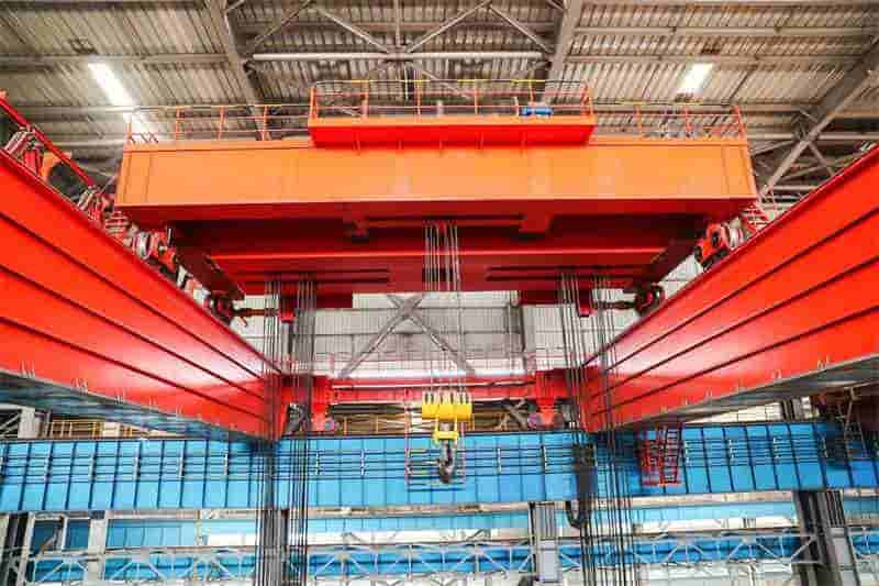
A double-girder bridge crane is a type of lifting equipment that is mounted horizontally above elevated tracks on either side of a building. It is commonly known as a “crane” or “trolley” because its supporting structures at both ends resemble a bridge. Compared to a single-girder crane, the double-girder design significantly improves equipment stability and load-bearing capacity by sharing the load between two parallel main girders. It is particularly suitable for industrial applications with large spans and heavy loads. A typical double-girder bridge crane consists of five major components: a metal structure (bridge), a hoisting mechanism, a trolley mechanism, a carriage mechanism, and an electrical control system. These systems work together to achieve precise material handling in three dimensions.
The design of a modern double-girder bridge crane begins with a comprehensive analysis of user requirements, including key parameters such as rated load capacity, operating class, span range, lifting height, and specific environmental requirements. For example, a 20t double-girder bridge crane is designed to efficiently replace traditional manual handling of heavy objects, significantly improving work efficiency and reducing labor intensity. The design process comprehensively considers the three major systems of mechanical structure, electrical transmission, and safety protection. Modern engineering methods such as computer-aided design (CAD) and finite element analysis are used to ensure the equipment’s reliability and safety under various operating conditions.
The operating class is a fundamental parameter in crane design, typically denoted by A1-A8. Higher numbers indicate more frequent operation and greater load variations. For example, a crane used in a general workshop might be classified as A3-A5, while a crane used in the metallurgical industry might require A6-A8. Designers must select the appropriate operating level based on the actual application scenario, which will directly impact subsequent motor selection, structural strength calculations, and component life assessments.
The design process for a double-girder bridge crane typically follows these steps: Determine design parameters → Overall design → Hoisting mechanism design → Trolley running mechanism design → Carriage running mechanism design → Bridge structure design → Electrical system design → Safety device design → Installation and commissioning plan development. Throughout the design process, standard components should be used as much as possible to improve design and manufacturing efficiency and reduce production costs. Furthermore, the design must adhere to relevant national standards and industry specifications, such as GB/T3811-2008 “Crane Design Code” and GB6067-2010 “Safety Regulations for Hoisting Machinery.”
It is worth noting that modern double-girder bridge crane designs have developed a variety of innovative structures, such as off-track box-type double-girder and truss-type double-girder. Each structure has its own specific advantages and application scenarios. Designers need to select the most appropriate structural form based on factors such as actual operating conditions, manufacturing costs, and ease of maintenance. This is a key topic discussed in detail in the following sections of this article.
The metal structure of a double-girder overhead crane forms the equipment’s skeleton and load-bearing structure. Its design directly determines the safety, reliability, and service life of the entire crane. The bridge, the primary load-bearing component, is meticulously constructed from two parallel main beams, two end beams (end beams), a platform, and guardrails, forming the basic framework supporting the entire crane. Depending on the cross-section of the main beam, it can be categorized as a box beam or a truss beam. The box beam is the most widely used due to its mature manufacturing process and high load-bearing capacity.
The box beam is the most common structural form of a double-girder overhead crane. It is welded together from an upper deck, web, lower deck, large and small ribs, and longitudinal tie bars. This closed box structure offers significant advantages, including high flexural and torsional rigidity, excellent stability, and mature manufacturing processes. When designing the main beam, the cross-sectional dimensions must be initially determined based on parameters such as the crane’s rated load, span, and operating class. Detailed strength, rigidity, and stability checks must then be conducted. Taking a 63/20T double-girder overhead crane with a 25.5m span as an example, its main girder design utilizes the allowable stress method. Through repeated verification, calculations, and dimensional adjustments, all parameters meet the material’s allowable requirements.
The main girder height-to-span ratio is typically controlled between 1/14 and 1/18. The web thickness is determined based on calculations but is generally no less than 6mm. The top cover is susceptible to instability due to compressive stress, so a sufficient number of stiffeners are required. The main girder is typically internally arranged with large and small stiffeners. The large stiffeners primarily bear vertical loads and prevent web buckling, and their spacing is generally no greater than the beam height. The small stiffeners primarily enhance the local stability of the web. In modern design methods, the main girder often utilizes an off-track design (where the tracks are not on the girder centerline). This structure effectively increases the girder’s lateral stability and facilitates trolley placement.
Strength calculations in main girder design primarily include verification of mid-span normal stress and span-end shear stress. Normal stress in the mid-span main beam consists of bending stress caused by vertical loads and additional stress caused by horizontal inertia forces, and must satisfy σmax ≤ [σ]. The web of the main beam at the end spans primarily bears shear stress, and must satisfy τmax ≤ [τ]. For cranes operating under heavy duty, fatigue strength calculations are also required, with a particular focus on the lifespan assessment of welds and stress concentration areas. Design data for a 10t-22.5m box-type double-girder bridge crane shows that its main beams are typically made of Q235B or Q345B steel. The latter offers higher strength but also requires more stringent welding procedures.
Calculating the main beam’s stiffness is also crucial, encompassing both static and dynamic stiffness. Static stiffness is measured by the vertical deflection of the main beam at mid-span under rated load, typically requiring a deflection no greater than 1/700 to 1/1000 of the span. Dynamic stiffness reflects the main beam’s ability to resist vibration and is assessed by calculating its natural frequency, generally requiring the first-order vertical natural frequency to be no less than 2Hz. The main beam is typically designed with an upward pre-arch at both ends, typically about 1/1000 of the span, to offset downward deflection under load and ensure smoother trolley operation.
The end beam is a key component that connects the two main beams to form a complete bridge. It not only bears the load transmitted by the main beams but also mounts the driving and driven wheel sets of the trolley mechanism. End beams are typically box-shaped, welded from steel plates. Each end beam is divided into two halves, rigidly welded to the ends of the main beams in an “I” shape. The two “I” halves are then connected with connecting plates and shear bolts to form the main frame structure.
End beam design must consider the combined effects of vertical and horizontal loads. Vertical loads include the crane’s own weight and the load of the trolley and hoisted load. Horizontal loads include the inertia of the trolley during braking and starting, lateral forces during skewed operation, and wind loads (for outdoor cranes). The connection between the end beam and the main beam is a stress concentration area, requiring special reinforcement and detailed strength verification of the connecting bolts or welds. The area on the end beam where the wheel assembly is mounted also requires local reinforcement to ensure it can withstand high contact stresses.
The end beam’s cross-section is typically smaller than the main beam, but its wall thickness should not be too thin, generally not less than 8mm, to ensure sufficient local stability. The end beam design also needs to consider the connection method to the main beam (welded or bolted), installation and maintenance space, and the placement of safety devices such as buffers. The rigid frame structure formed by the end beam and main beam is the foundation of the high stability of double-girder bridge cranes. This structure enables the crane to effectively resist lateral forces and prevent overall instability.
Modern double-girder bridge cranes have developed a variety of innovative structures based on the traditional box beam to further improve performance or reduce deadweight. The offset track box beam double beam is a typical innovative design. The track is located above the main beam web, rather than in the center of the traditional upper deck. This arrangement increases the main beam’s lateral bending resistance and simplifies the trolley’s operating mechanism. Another innovation is the use of a truss-type main girder. This structure, constructed from a system of rods forming a spatial truss, replaces the solid-web box girder. This structure offers low weight and reduced wind resistance, making it particularly suitable for cranes with large spans and outdoor applications.
Double-girder bridge cranes offer significant advantages over single-girder structures: Two main girders share the load, reducing single-point stress; the double girders and end beams form a rigid framework, enhancing overall stability; and the box-shaped structure and strategically placed internal stiffening ribs significantly enhance the main girder’s bending resistance. These advantages make double-girder bridge cranes particularly suitable for applications with large tonnage, long spans, and heavy duty loads.
Table: Performance comparison between box girder and truss girder
| Feature | Box main beam | Truss main beam |
| Manufacturing process | The welding process is mature and suitable for mass production | There are many rods, complex nodes, and long manufacturing time |
| Structural deadweight | Larger, more consumables | Lighter, saving 20%-30% of steel |
| Torsional stiffness | Very good | Relatively poor, requires special design |
| Wind resistance characteristics | Large frontal area and high wind resistance | Pole system, low wind resistance |
| Maintenance convenience | The interior is difficult to inspect and requires high anti-corrosion | Exposed rods for easy inspection and maintenance |
| Applicable scenarios | Small and medium span, mainly for indoor use | Large span, better for outdoor use |
Modern design methods also incorporate optimization algorithms and finite element analysis techniques. Through parametric modeling and stress cloud analysis, they identify the optimal main beam cross-sectional dimensions and stiffening rib layout, reducing the structure’s deadweight while ensuring strength and rigidity. Furthermore, the application of computer-aided design (CAD) technology has significantly improved design efficiency, enabling the rapid generation of detailed construction drawings. The design of metal structures also needs to consider manufacturing processability, employing standardized and modular design approaches whenever possible, minimizing the need for specialized components and complex welds to reduce manufacturing costs and improve production efficiency.
The hoisting mechanism is the core working component of a double-girder bridge crane, responsible for vertically lifting and lowering the load. The reliability of its design directly determines the safety and efficiency of the entire crane. The hoisting mechanism typically consists of key components such as the drive motor, reducer, brake, drum, wire rope, pulley block, and hook assembly. The proper selection and matching of these components is crucial to ensuring mechanism performance. Depending on the lifting capacity, a crane may be equipped with a single hoisting mechanism or a dual hoisting mechanism with a primary and secondary hook. Cranes of 15 tons and above are typically equipped with two hoisting mechanisms (a primary hook and a secondary hook) to enhance operational flexibility and efficiency.
The design of the hoisting mechanism transmission solution is the first step in the overall design process, requiring comprehensive consideration of factors such as the lifting capacity, operating level, speed requirements, and space constraints. A typical transmission solution utilizes a motor connected to the reducer via a coupling and a brake pulley. The reducer’s output shaft is connected to the drum, which carries the wire rope, via a drum coupling. As the motor drives the drum to rotate, the wire rope winds or unwinds on the drum, raising and lowering the hook. In the design of the trolley hoisting mechanism for a 5T double-girder overhead crane, we first analyzed domestic and international crane development trends and operating principles to develop an overall design plan and preliminary selection of key components.
Hoisting mechanism layouts can be divided into two basic types: parallel-axis and coaxial. In the parallel-axis arrangement, the motor axis is parallel to the drum axis, and speed and torque conversion is achieved through a reducer. This arrangement is compact and easy to maintain, making it the most commonly used arrangement for double-girder overhead cranes. In the coaxial arrangement, the motor axis coincides with the drum axis, and they are connected via a planetary reducer or special coupling. This arrangement saves space but is difficult to maintain, and is often used in space-constrained applications. The design process requires selecting the most appropriate layout based on the structural characteristics of the trolley frame, ensuring that the mechanism and steel structure complement each other, meeting functional requirements while simplifying the structure.
The wire rope is a key load-bearing component in the hoisting mechanism, and its selection directly affects the crane’s safety performance. Wire rope selection is typically based on the maximum operating tension and a safety factor, which is generally no less than 5-6 (adjusted according to the operating level). When calculating the maximum working tension, factors such as the rated load, pulley block ratio, sling weight, and wire rope efficiency must be considered. For example, if a 5-ton crane uses a double pulley block with a ratio of 4 and a wire rope efficiency of 0.97, the maximum static tension of a single wire rope, S, is calculated as (Q + q) / (2mη) = (50,000 + sling weight) / (2 × 4 × 0.97).
The pulley block design consists of a fixed pulley and a movable pulley. The fixed pulley is fixed to the trolley frame, while the movable pulley moves with the hook. The pulley diameter D must satisfy D ≥ (h-1)d, where h is the ratio of the pulley diameter to the wire rope diameter (usually 20-30), and d is the wire rope diameter. Pulleys are commonly made of cast iron or cast steel. Large pulleys can be welded to reduce weight. In the design and fabrication of a fixed pulley for a 1510t double-girder hook bridge crane, a mechanical graduation project, the designers conducted detailed design of the fixed pulley assembly, including the pulley structure, bearing selection, and installation method, and expressed the design intent through CAD drawings.
The pulley shaft design requires calculation of bending and shear stresses, with particular attention to stress concentration at the bearing mounting point. The pulley shaft length should be appropriately determined to ensure adequate installation space for the pulley while avoiding insufficient rigidity due to excessive shaft length. Spherical roller bearings are typically used to compensate for misalignment caused by installation errors and shaft deformation. The fixed pulley mounting method should facilitate adjustment and maintenance while ensuring sufficient structural strength.
The drum is the component of the hoisting mechanism used to wind and store wire rope. Its design must consider parameters such as rope capacity, diameter, length, and wall thickness. The drum diameter D should be no less than 20 times the wire rope diameter d (i.e., D ≥ 20d) to reduce bending stress on the wire rope. The drum length depends on the lifting height, pulley ratio, and wire rope diameter. Ensure that at maximum lifting height, at least two to three safety turns remain on the drum. The drum wall thickness must be strength-checked, especially in areas subject to significant compressive stress. Finite element analysis can be used for detailed analysis.
Drive component selection includes the motor, reducer, and brake. Motor power calculations must consider the rated lifting speed, overall mechanism efficiency, and the required maximum static power. The formula is P = (Q + q)v / (6120η), where Q is the rated lifting capacity (kg), q is the weight of the hoisting device (kg), v is the lifting speed (m/min), and η is the overall mechanism efficiency. The motor also requires thermal and overload checks to ensure it meets the required operating level. Reducers can be selected from standard or custom designs based on the required transmission ratio, input speed, and output torque.
The brake is a safety feature of the lifting mechanism and is typically a normally closed brake that automatically engages upon power failure. For cranes with intermediate or higher operating levels, dual braking is recommended. This means that in addition to the conventional motor shaft brake, a safety brake is also installed on the low-speed shaft. The braking torque should be at least 1.5-2 times the maximum static torque to ensure reliable braking. Modern cranes are also often equipped with electronic brake control systems for smooth braking and anti-sway functions.
Table: Key points for design of main components of lifting mechanism
| Part | Design Points | Calculation formula/standard | Precautions |
| Wire rope | Diameter, structure, tensile strength | Safety factor n≥S breaking/S maximum ≥5-6 | Consider fatigue life and wear resistance |
| Pulley block | Diameter, material, bearing selection | D≥(h-1)d, h=20-30 | The mass effect of the movable pulley needs to be calculated |
| Reel | Diameter, length, rope capacity | D≥20d, L=Hm/πD+n(t+d) | Rope groove and pressure plate are required at the end |
| Electric Motor | Power, speed, duty cycle | P=(Q+q)v/(6120η) | Heating and overload capacity need to be verified |
| Reducer | Transmission ratio, torque, service factor | i=n motors/n reels | Select by actual work level |
| Brakes | Braking torque, braking time | M制≥KZ×M静, KZ=1.5-2 | Normally closed, double braking is safer |
The overall layout of a hoisting mechanism requires comprehensive consideration of the positional relationships between various components and maintenance clearance. As a design principle, the mechanism should be the primary focus, with the trolley frame being used to complement the mechanism whenever possible. Furthermore, the mechanism layout should be coordinated with the trolley frame design to ensure a simple, rational, and easily manufactured structure. In a parallel-axis arrangement, the motor, reducer, and drum are typically placed in the same plane, connected by a coupling, with the brake mounted on the other end of the motor. This arrangement offers a compact structure and high transmission efficiency, making it the preferred solution for most double-girder bridge cranes.
Modern hoisting mechanism design emphasizes modularity and standardization, utilizing standard components whenever possible to improve design and manufacturing efficiency and reduce production costs. For example, using a standard reducer rather than a custom one, while potentially compromising size, can significantly reduce costs and shorten delivery cycles. Another optimization area is reducing the mass of moving parts, particularly the hook assembly and movable pulley. This reduces inertial loads and improves energy efficiency.
Histing mechanism control methods are also evolving with technological advancements. Traditional resistance-controlled speed regulation has been gradually replaced by variable-frequency speed regulation. Frequency conversion control enables stepless speed regulation and smooth starting and braking of the hoisting mechanism, significantly reducing dynamic loads and mechanical shock. Furthermore, intelligent control systems can implement advanced features such as spreader anti-sway, automatic positioning, and load anti-sway, significantly improving production efficiency and operational safety. These electrical control innovations must be considered simultaneously with mechanical design to ensure a perfect fit between hardware structure and control strategy.
The horizontal movement of a double-girder overhead crane is accomplished by the trolley and gantry mechanisms. Working together, they cover the entire three-dimensional space of the work area. The trolley mechanism drives the trolley for lateral movement along the main girder rails, while the gantry mechanism drives the entire crane for longitudinal movement along the plant rails. Although these two mechanisms have similar functions, they differ significantly due to varying loads and operating conditions. A well-designed mechanism should ensure smooth starting and braking, minimal operating resistance, even wheel wear, and reasonable noise levels.
The trolley mechanism is the key component that enables lateral movement of the load. It primarily consists of a motor, reducer, wheels, and frame. When designing the trolley mechanism, the following key factors should be considered:
The trolley mechanism is the longitudinal moving part of a double-girder bridge crane, and its design is equally crucial. The trolley mechanism primarily consists of driving wheels, driven wheels, tracks, and the crane body. When designing the trolley mechanism, the following aspects should be considered:
Contact our crane specialists
Send us a message and we will get back to you as soon as possible.