Home → News → Double-girder bridge crane installation and construction plan
Double-girder bridge crane installation and construction plan
I. Project Overview
1. Project Introduction
This project involves the installation of double-girder bridge cranes for the filling and machine repair shops of Inner Mongolia Lantai Industrial Co., Ltd.’s 12,000-ton high-quality liquid sodium project. Specifically, it involves the installation and construction of two 50-ton double-girder bridge cranes in the filling shop and one 16-ton double-girder bridge crane in the machine repair shop.
2. Equipment Overview and Main Technical Parameters
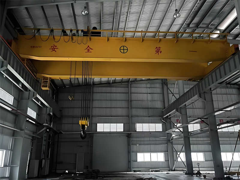
2.1 Double-Girder Bridge Crane Structure
A double-girder bridge crane primarily consists of three parts: the hoisting mechanism, the operating mechanism, and the bridge structure. The specific components are as follows:
Hoisting mechanism: includes the motor, brake, reducer, drum assembly, fixed pulley assembly, hook assembly, hoist limiter, transmission, and coupling.
Operating mechanism: includes the motor, brake, reducer, drive shaft, coupling, and wheel assembly. The trolley is centrally driven, while the trolley is individually driven.
Bridge structure: includes the main beam, end beams, platform, cable carriage, driver’s cab, ladder railing platform, etc.
2.2 Equipment Technical Parameters
16T Double-Girder Bridge Crane
Serial number
Parameter name
Parameter performance (capacity)
1
Type and model
QD16/3.2t bridge crane
2
Span
10.5m
3
Working Level
A5
4
Rated lifting capacity
16/3.2t
5
Lifting height
Main hook: 7.2m; auxiliary hook: 7.5m
6
Lifting (lowering) speed
Main hook: ≤0.78~7.8m/min; Auxiliary hook: ≤0.93~9.3m/min
7
Operation
Aerial and ground control (with remote control)
8
Running speed
Trolley Travel: 70m/min; Crab Travel: 26.3m/min
9
Trolley track model
43kg/m
50T explosion-proof double-girder bridge crane
Serial number
Parameter name
Parameter performance (capacity)
1
Type and model
QB50/10t double girder bridge crane
2
Span
16.5m
3
Working Level
A4
4
Rated lifting capacity
50/10t
5
Lifting height
Main hook: 11m; auxiliary hook: 12m
6
Lifting (lowering) speed
Main hook: 0.25~2.5m/min; Auxiliary hook: 0.27~2.7m/min
Based on the volume of crane installation work, we plan to staff on-site management personnel and relevant technical personnel, including one project manager, one supervisor each, three installers, two riggers, three electricians, and three general workers.
2. Total Construction Duration
30 working days from the effective date of the contract, i.e., from August 1, 2016, to August 30, 2016. If production needs require a shorter construction period, additional technical personnel may be added at any time to ensure that the installation is completed within the required timeframe.
3. Main Construction Equipment and Inspection Instruments
3.1 Main Construction Equipment
Serial number
Device Name
Equipment Capabilities
Number of devices
1
Truck crane
50T
2 units
2
Chain hoist
5t、10t
2 units each
3
Jack
10t
4 units
4
Welder
Manual welding machine
2 units
5
Bench tools
Tool kit
2 sets
6
Electrician tools
Tool kit
2 sets
7
Scaffold
1 sets
3.2 Main inspection instruments and measuring tools
Serial number
Instrument name
Instrument and equipment capabilities
Number of instruments and equipment
1
Theodolite
1
2
Level
1
3
Frame level
250×250
1
4
Multimeter
1
5
Clamp-type ammeter
1
6
Ground resistance meter
1
7
Insulation resistance tester
1
8
Magnifier
20 times
1
9
Steel tape measure
50m
1
10
Steel tape measure
5m
2
11
Steel ruler
1m
1
12
Square (grade 2 or above)
315×200
1
13
Vernier caliper
0.02mm(0.03mm)×0-350mm
1
14
Feeler gauge
1
15
Steel wire
φ0.49-φ0.52
1 plate
16
Tension scale
150lg
1
17
Dial indicator
0-10min
1
III. Quality and Safety Assurance Measures
1. Quality
Overhead crane installation must be carried out under the control of quality inspection and technical personnel, strictly in accordance with drawings and specifications.
2. Safety
Safety Policy: People-oriented, safety paramount.
Safety Goal: Achieve the “Three No-Injuries” (no harm to self, no harm to others, no harm by others).
Responsible Personnel: The project manager is the primary responsible person, and a dedicated safety officer is responsible for implementation and supervision.
3. Specific Requirements and Precautions
Training: All construction personnel must undergo rigorous training and pass the training before they can begin work.
Lifting Rigging: All lifting rigging must have a safety factor of at least 5 times, and lashing wire must have a safety factor of at least 10 times.
Cordon: The construction area must be cordoned off and supervised by designated personnel. Non-construction personnel are strictly prohibited from entering.
Lifting Operations: Lifting personnel must adhere to the “Ten No-Lifting” principle. Commanders must give clear instructions, and operators must concentrate and operate diligently. Electrical safety: Non-electrical personnel are not allowed to operate electricity privately. Standard distribution boxes must be installed on site, and cable laying must comply with standard regulations.
IV. Crane Installation Plan Development
1. General
Standards: Ensure the installation process complies with ISO9001 quality system standards and the Coal Mine Safety Regulations.
Inspection Specifications: After installation is completed, inspection and testing must be conducted in accordance with the “Specifications for Construction and Acceptance of Crane Equipment Installation Projects.”
2. Installation and Acceptance Standards
GB3811 Crane Design Specifications
GB6067 Hoisting Machinery Safety Regulations
GB/T14405 General-Purpose Bridge Cranes
JB 5897 “Explosion-Proof Bridge Cranes”
GB50256 Electrical Equipment Construction and Acceptance Specifications
GB5905 Crane Test Specifications and Procedures
GB50278 Crane Installation Project Construction and Acceptance Specifications
3. Implementation Plan Overview
Document Review: This includes equipment quality certificates, installation (operation) instructions, product electrical wiring diagrams, product electrical schematics and symbol descriptions, and component installation drawings.
Notification and Approval: Written notification to the special equipment safety supervision and management department is required prior to installation, and approval procedures must be completed. Technical Briefing: Before installation, the construction equipment and measuring instruments must be verified and a technical briefing must be conducted.
Equipment and Material Acceptance: Personnel from the owner, supervisor, construction company, and manufacturer will conduct an on-site inventory inspection to confirm that all parts are complete and meet quality standards before installation can begin.
V. Emergency Measures
1. Object Impact Accident Prevention and Emergency Plan
Safety Requirements: Wear a hard hat when entering the construction site. Do not throw materials randomly. Be careful of falling parts during overhead installation to prevent injury.
2. Electric Shock Accident Prevention
Safety Requirements: Non-electricians are strictly prohibited from connecting or disconnecting electrical wiring. Maintain a safe distance between live parts, display clear signs, and implement insulation and protective grounding measures.
3. Emergency Rescue Measures
Fire Accident: Immediately disconnect the power supply, call 119, and use on-site fire extinguishers.
Personal Injury Accident: Immediately report the incident and notify a hospital for on-site rescue.
Equipment Accident: Immediately disconnect the power supply, stop equipment, and report to the construction manager.
VI. Process Flow
1. Construction Preparation
Tool Inspection: Major construction tools and sub-processes must undergo testing and inspection.
Track Inspection: The trolley track must be inspected and accepted by the owner and the supervising engineer.
Personnel Training: All installation personnel must be certified and trained.
2. Bridge Inspection Methods
Girder Mid-Span Camber Inspection: Measure using a 0.49-0.52mm diameter steel wire with a pull of 150N.
Girder Web Local Warping Inspection: The measurement direction and location can be arbitrarily selected, but must not cross the H/3 limit from the upper deck.
Girder Horizontal Bend Inspection: Secure a 0.5mm diameter steel wire or 0.5mm diameter nylon thread with a clamp and measure at a pull of 100N.
Bridge Diagonal Inspection: Locate the wheel center at the wheel bend and measure the lengths S1 and S2 with a steel tape measure.
3. Crane Installation Process Sequence
Girder Hoisting: Select the lifting point, secure with wire rope, and hoist the main beam using an explosion-proof manual hoist. Adjust the main beam angle and then place it on the track.
Trolley Hoisting: Determine the working position of the explosion-proof manual hoist, lift the trolley, adjust the angle, and align it with the track.
Ancillary Facilities Installation: Includes walkway railings, ladders, conductive wire guards, lifting limit switches, safety gauges, and wire rope wrapping.
Electrical Installation: Includes electrical equipment installation, wiring and conduit installation, wiring, and safety grounding.
4. Crane Trial Run
Inspection: Includes the installation quality and operation of the crane’s mechanical and electrical components, as well as safety devices.
Trial Run Steps: Includes a no-load test run, a static load test, and a dynamic load test run.
△S=5, but the difference between the span value of the driving wheel and the span value of the driven wheel shall not exceed 5mm
2
Camber of main beam after assembly
F=(0.9/1000-1.4/1000)S
3
Bridge diagonal deviation │D1-D2│
│D1-D2│≤5, symmetrical box beam: f≤1/2000S
4
Horizontal lateral curvature of main beam (after platform and end beam are installed)
│D1-D2│≤5, symmetrical box beam: f≤1/2000S
5
Trolley gauge deviation
Symmetrical box beam: span: ±2+5, outside the span: S≤19.5mm+1+7, S>19.5mm+1
6
Height difference of trolley track with the same cross section
Symmetrical box beam: span: ±2+5, outside the span: S≤19.5mm+1+7, S>19.5mm+1
7
Position deviation between the center line of the trolley track and the center line of the track beam web
Off-track box girder: δ<12, d≤6; δ≥12, d≤1/2δ; single web girder and frame: d≤1/2δ
2. Electrical Equipment Requirements
Design Standards: Comply with GB3811, GB6067, and the Coal Mine Safety Regulations.
Power Supply: Three-phase AC, 380V ± 10%, 50Hz.
Electrical Protection: Includes short-circuit and overload protection, undervoltage protection, emergency power-off protection, hoist and travel limit protection, door switch protection, and overload protection.
Grounding Requirements: The crane’s metal structure and the metal casing of all electrical equipment must be reliably grounded, with a grounding resistance of no more than 4 ohms.
Ⅷ. Completion and Acceptance
Self-Inspection and Corrective Actions: Promptly correct any supervisory observations made during the inspection process, conduct a thorough self-inspection, and complete a “Self-Inspection Report.”
Inspection and Acceptance: After passing the self-inspection, submit the inspection report to the crane user and apply for quality inspection by the special equipment inspection department of the local and municipal quality and technical supervision bureaus. After passing the inspection, the construction company submits a formal acceptance report and relevant materials to the crane user. The handover of these materials requires signatures from representatives of both parties.
The above details the installation and construction plan for a double-girder overhead crane, covering all aspects of the project, including project overview, specific work arrangements, quality and safety assurance measures, installation plan development, emergency response measures, process flow, quality requirements, and completion and acceptance, ensuring a standardized and safe construction process.
Contact our crane specialists
Send us a message and we will get back to you as soon as possible.