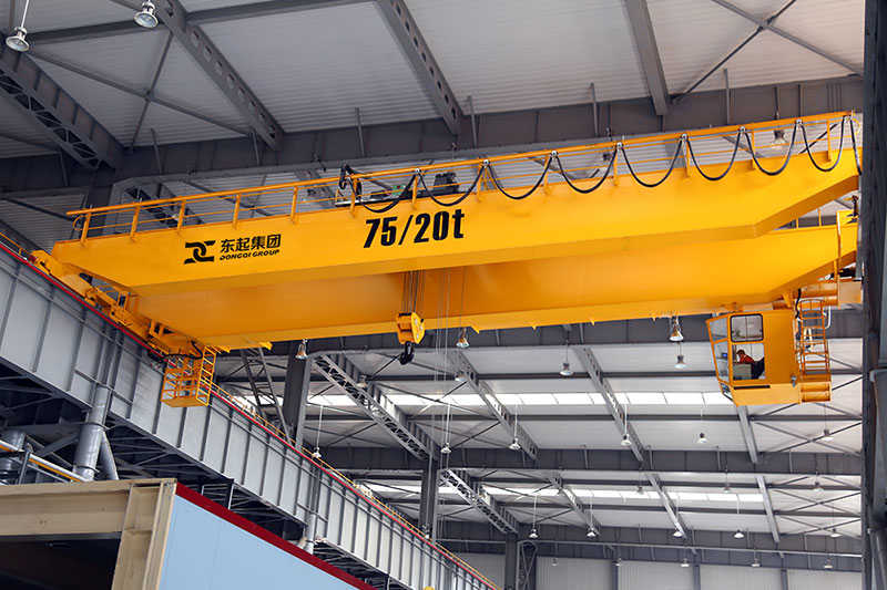
As a core piece of heavy-duty industrial material handling equipment, the 80/30T 28m universal bridge crane plays a key role in modern manufacturing. Featuring a double-girder box-type design, it boasts a main lifting capacity of 80 tons, an auxiliary hook lifting capacity of 30 tons, and a span of 28 meters, meeting the heavy-duty demands of large workshops, ports, and terminals. Designed in strict compliance with the GB/T 14405-2011 “General-Purpose Bridge Crane” standard, it integrates modular design concepts and finite element optimization technology to achieve a breakthrough balance between structural strength, operational stability, and energy efficiency. Equipped with a variable frequency speed control system and multiple safety features, the crane adapts to the complex operating conditions of precise lifting and high-intensity continuous operation. Its technical parameters and performance indicators reach the internationally advanced level of similar products.
The 80/30T 28m universal bridge crane is a heavy-duty industrial lifting equipment designed to meet the demands of high-intensity, high-precision, and large-tonnage material handling. This crane features a double-girder design with a main span of 28 meters, enabling it to cover a wide working area. Its rated lifting capacity is 80 tons with a main hook and 30 tons with an auxiliary hook, meeting the needs of most heavy material handling operations.
A key feature of this crane is its fully variable speed control, enabling millimeter-level control accuracy. This ensures smoother and more accurate lifting and transport operations, preventing material sway or damage caused by speed fluctuations. Furthermore, the crane is equipped with various safety features, such as overload protection and position limit protection, to ensure safe operation.
This crane is suitable for heavy material handling operations in industries such as metallurgy, power generation, and machinery manufacturing. Cranes are essential equipment in these industries, improving production efficiency and reducing costs. The crane reduces worker workload and enhances operational safety.
The bridge, a core component of the crane, utilizes a composite box girder and truss structure. This structural design ensures load-bearing strength while optimizing deadweight, reducing energy consumption and maintenance costs. The entire crane achieves A6 operating class, capable of meeting the requirements of a variety of demanding working environments.
Targeting the material handling needs of heavy industrial applications, this model focuses on addressing stability and precision control during large-tonnage lifting operations. In steel mills, this crane can be used for specialized applications such as ladle transfer, generator stator installation in power plants, and large component assembly in heavy machinery manufacturing workshops. These applications place high demands on crane performance and reliability, requiring high strength, high precision, and a large tonnage capacity.
During the design process, special consideration was given to equipment reliability in harsh environments such as high temperatures and high dust levels. The use of advanced materials and process technologies ensures the crane maintains stable performance and longevity in these harsh environments. Furthermore, emphasis was placed on ease of maintenance and servicing to facilitate long-term use and upkeep.
The crane’s key technical parameters and performance indicators include: rated load, lifting height, operating speed, trolley speed, dynamic rigidity, and deadweight. These parameters and indicators are crucial criteria for measuring crane performance and are key factors to consider during the design process. Specifically, this crane has a rated lifting capacity of 80 tons with a main hook and 30 tons with an auxiliary hook, meeting the needs of most heavy material handling operations. Its lifting height is 16 meters with a main hook and 18 meters with an auxiliary hook, accommodating material handling needs at various heights. Operating speeds for the main hoist are 3.2 meters per minute (fully loaded) and 7.5 meters per minute (unloaded), while the trolley travels at a speed of 45 meters per minute (variable frequency speed regulation). These specifications ensure efficient operation and productivity.
In addition, the crane’s dynamic rigidity is specified as a mid-span static deflection ≤ L/800 and a deadweight of ≤ 168 tons (including all mechanisms). These indicators ensure its stability and reliability. During the design and manufacturing process, other factors, such as structural rationality, material selection, and manufacturing processes, were also considered to ensure the crane’s high performance and long-term stability.
This crane’s design strictly adheres to the dual standards of GB/T 14405-2011, “General-Purpose Bridge Cranes,” and FEM 1.001-1998, “European Code for Crane Design.” In terms of structural design, the allowable stress method was used for steel structure calculations, ensuring a safety factor of ≥1.48 for all load-bearing components. This means that under normal operating conditions, the crane has sufficient safety margins and stability.
The crane’s electrical system is designed in strict accordance with IEC 60204-32 explosion-proof requirements, ensuring safe and reliable operation even in flammable and explosive environments. Furthermore, the electrical system’s protection level meets IP55 standards, effectively preventing the intrusion of moisture and dust, enhancing equipment reliability and durability. Furthermore, the crane is equipped with a variety of safety protection devices and a monitoring system that monitors the equipment’s operating status and working environment in real time, enabling the timely identification and resolution of potential safety hazards.
Table: Comparison of main technical parameters of 80/30T 28m general bridge crane
| Parameter Category | Main hook parameters | Auxiliary hook parameters | Design standards | Structural characteristics | Electrical system standards |
| Rated lifting capacity | 80 ton | 30 ton | GB/T 14405-2011 | Box beam and truss composite structure | IEC 60204-32 |
| Lifting height | 16m | 18m | FEM 1.001-1998 | Span 28 meters | IP55 protection level |
| Working speed (full load) | 3.2 m/min | _ | Safety factor ≥1.48 | Dynamic rigidity ≤ L/800 | Full frequency conversion speed regulation |
| Working speed (no load) | 7.5 m/min | _ | _ | Equipment weight ≤ 168 tons | Millimeter-level control accuracy |
| Trolley running speed | 45 m/min (frequency control) | _ | _ | Working level A6 | Overload/limit protection |
Table: 80/30T 28m general bridge crane application and performance analysis table
| Application Areas | Typical working conditions | Core Advantages | Environmental adaptability | Security Features | Maintenance costs |
| Metallurgical Industry | Ladle transfer | Large tonnage and high precision lifting | High temperature resistant design | Real-time operation status monitoring | Structural deadweight optimization |
| Power Industry | Generator stator hoisting | Double hook collaborative operation | Anti-dust intrusion | Multiple electrical protection | Modular component design |
| Mechanical Manufacturing | Large component assembly | Excellent dynamic rigidity | Vibration resistance | Emergency braking system | _ |
| General Industry | Heavy material handling | Full frequency conversion speed regulation stability | Compatible with explosion-proof environments | Sound and light alarm device | Low energy operation |
The main girder is welded from Q345B steel plates into a box-shaped variable-section structure, which offers high strength and stability. The web thickness varies gradually from 16 to 24 mm, allowing for adjustment based on load conditions and improving material utilization. The upper flange is 1200 mm wide and features T-shaped reinforcement ribs, increasing the main girder’s rigidity and load-bearing capacity. The end girder is a double-web box-shaped structure with internal torsion-resistant bulkheads. High-strength bolted flange connections to the main girder ensure high strength and reliability. A pre-set camber of L/1000 is established at mid-span. Finite element analysis has verified that deformation under extreme loads does not exceed L/750, ensuring the main girder maintains excellent deformation performance under load.
The main hoisting mechanism is driven by four 200kW variable-frequency motors, a planetary reducer with a transmission ratio of i=63.5, and a double-wound system with 42mm diameter 35W x 7 steel wire ropes. This design ensures the crane’s lifting speed and stability. The drum is made of ZG340-640 cast steel, and the rope groove surface is hardened to HRC45-50, enhancing its wear resistance and service life. The balance pulley is forged from nickel-chromium alloy steel and equipped with self-lubricating bearings to ensure balance and stability.
The trolley frame is a one-piece welded structure, with 45kW drive motors located at each corner, directly driving the wheels via a three-in-one reducer. This design ensures both speed and stability. The wheels are made of ZG50SiMn alloy steel, with a tread hardness of HB320-380. The double-rim design ensures accurate running trajectory. The QU100 rails are designed with joint misalignment controlled to within 2mm, ensuring accurate trolley running trajectory.
The trolley utilizes an eight-point drive arrangement, with each drive unit consisting of a 55kW variable-frequency motor, a hardened gear reducer, and a hydraulic push rod brake. This design ensures both speed and stability. The wheel assembly is equipped with a spherical hinge balance beam device, which allows for ±3mm track height difference compensation to ensure the smooth operation of the trolley. Polyurethane buffers are installed at both ends of the end beam, with an energy absorption capacity of ≥15kJ, to absorb impact energy during trolley operation and improve operational safety.
The main hoist mechanism uses a YZP355L-8 variable-frequency motor. This eight-pole motor offers a wide speed range and excellent speed regulation, meeting the demands of various operating conditions. Its insulation rating is H, indicating the motor’s internal use of high-performance insulation materials, ensuring excellent insulation performance even in high-temperature environments and effectively preventing insulation aging caused by high temperatures. Its IP54 protection rating ensures the motor is waterproof and dustproof, ensuring normal operation even in harsh environments. Furthermore, the motor is equipped with a temperature sensor and a vibration monitoring module. This module monitors the operating status in real time through a PLC, enabling precise control of motor temperature and vibration, effectively preventing failures caused by overheating or abnormal vibration. To enhance system stability and reliability, all motors are equipped with vibration isolation pads to effectively reduce structure-borne noise, ensuring smoother and quieter operation. Reducer Design and Selection
The hoisting mechanism reducer utilizes a NAD560 planetary gearbox, achieving Class 6 gear accuracy (GB/T10095), ensuring high-precision transmission and enhancing system stability and service life. The housing is constructed of cast iron for high strength and wear resistance. A circulating oil lubrication system ensures the reducer remains well lubricated even under prolonged, high-intensity operation, effectively reducing wear and extending service life. The operating mechanism utilizes a three-in-one reducer motor, integrating the motor, reducer, and brake into a single unit. This significantly simplifies the transmission structure, reducing size and weight. Its built-in helical gear transmission design achieves a mechanical efficiency of ≥94%, improving system energy efficiency.
The high-speed shaft utilizes an NL-type gear coupling, which offers high transmission efficiency and ensures efficient operation of the power system. The gear coupling also offers excellent angular compensation, allowing for 0.5° of angular misalignment, effectively minimizing the impact of installation errors or angular misalignment during operation on system performance. The braking system is equipped with a YWZ5-500/80 electro-hydraulic actuator. This brake features an adjustable braking torque range of ±15%, enabling precise adjustment based on actual needs, ensuring reliable braking under diverse operating conditions. Its friction pads are made of high-temperature-resistant material with a temperature resistance of over 350°C, maintaining excellent braking performance even in high-temperature environments. To further enhance the safety of the braking system, it can reliably brake at 1.5 times the rated load during emergency braking, ensuring a quick and safe stop in any situation.
Matlab simulations calculated the overall transmission efficiency of the machine: 88.7% for the hoisting mechanism and 91.2% for the operating mechanism. To further improve transmission efficiency, key improvements include using a gear grinding process to enhance gear meshing efficiency and replacing sliding bearings with rolling bearings to reduce friction losses. These improvements effectively enhance the system’s transmission efficiency and overall performance, making the entire powertrain and transmission more efficient, stable, and reliable.
For height control of the hoisting mechanism, an advanced absolute encoder is used as the primary limiter. It features high accuracy and excellent stability, providing precise real-time hook position information. Furthermore, to ensure safety redundancy and reliability, a mechanical fire-break switch is added as a secondary limiter. If an encoder fails, this switch disconnects the power circuit to prevent overload. High-performance laser rangefinder systems are installed at both ends of the trolley’s travel path. They accurately measure the distance traveled by the trolley and work in conjunction with the hydraulic buffers to provide gentle and efficient braking. The buffers have ample travel (≥150mm) to effectively absorb kinetic energy, ensuring deceleration is kept within 0.3g near the end of travel.
To prevent the crane from tipping over during operation, an anti-tipping warning system consisting of a torque limiter and a spirit level is installed. This system monitors the crane’s tilt in real time. If the tilt angle exceeds a preset threshold (e.g., 0.5°), an alarm is triggered, prompting the operator to adjust their working posture. Furthermore, to address the potential loss of crane stability during strong winds, a windproof securing system has been designed. This system includes electric rail clamps and anchoring holes. In strong winds, the electric rail clamps automatically clamp the rails, securing the crane in place. The anchoring holes serve as auxiliary anchoring points. Through a well-designed anchoring structure and connectors, the crane maintains stability in strong winds, achieving a wind pressure resistance of 11 (800 Pa).
To effectively monitor and prevent safety hazards caused by excessive lifting loads, a high-precision strain gauge sensor is used to measure the actual load weight on the hook in real time. With an accuracy of ±1% FS (full scale), this sensor ensures high sensitivity and accuracy in overload protection. When the load exceeds 105% of the rated value, a three-level warning mechanism is triggered: first, an audible and visual warning signal is issued, prompting the operator to take immediate action to reduce the load. If the load still does not fall within a safe range, the speed reduction process is automatically initiated. If the load continues to increase to a dangerous level, the power supply is finally cut off to maximize the safety of equipment and personnel. In addition, the overload alarm system uses a standard 4-20mA analog interface for signal output, allowing for easy connection to the DCS (Distributed Control System) in the central control room for remote monitoring and recording.
The cab is equipped with a panoramic monitoring system, providing full visibility and eliminating safety hazards caused by blind spots. It also features an anti-incorrect operation interlock to ensure that multiple critical operating steps are performed in the correct sequence, preventing accidents caused by incorrect operation. For the safety and convenience of maintenance personnel, permanent anti-fall guardrails are installed in the maintenance access, which have been rigorously tested to meet a load-bearing requirement of at least 400kg/m². All maintenance platforms are designed and constructed to high standards to ensure stable load-bearing capacity during long-term use. In addition, the electrical cabinet door is equipped with a safety interlock switch and an automatic power-off function when the door is opened. When the cabinet door is opened, the relevant power circuit will be automatically cut off to prevent accidental electric shock or short circuit accidents.
Table: Safety protection device list (lifting equipment)
| Device Type | Specific device/system | Technical parameters/function description | Trigger conditions/protection mechanisms | Redundant design/auxiliary measures | Risk resistance level/standard |
| Limit control | Absolute encoder | High precision, good stability, and real-time hook position | Real-time location monitoring | Mechanical ignition cut-off switch as auxiliary limit | Overload protection standard EN 60204-1 |
| Limit control | Laser rangefinder + hydraulic buffer | Buffer stroke ≥150mm, deceleration ≤0.3g | Truck travel end point detection | Hydraulic cushioning absorbs kinetic energy | Braking performance in accordance with ISO 12488-1 |
| Anti-roll system | Torque limiter + level | Real-time monitoring of tilt angle | Tilt angle ≥ 0.5° triggers alarm | Electric rail clamp + anchor pit double fixation | Anti-tilt coefficient ≥1.5 (ISO 4304) |
| Windproof device | Electric rail clamp | Automatic clamping rail | Wind speed ≥ 11 wind pressure (800Pa) | Anchor pit auxiliary fixation | Wind resistance level 11 (GB/T 3811-2008) |
| Overload protection | Strain gauge sensors | Measurement accuracy ±1%FS | Load > 105% of rated value: Sound and light alarm → Speed reduction → Power cut off | 4-20mA signal access to DCS | Safety factor 1.25 (FEM 1.001) |
| Security Monitoring | Panoramic monitoring system | No blind spot coverage | Real-time video surveillance | Anti-misoperation interlock device | Protection grade IP65 (IEC 60529) |
| Electrical safety | Safety interlock switch | Automatic power off when door is opened | Cut off power when the door is opened | Double insulation design | Compliant with IEC 61439-1 |
| Maintaining safety | Fall prevention guardrail | Load bearing ≥400kg/m² | Permanent protection | High-strength design of maintenance platform | Load test standard EN 1991-1-1 |
Table: Comparison of performance parameters of safety protection devices
| Device Name | Core performance indicators | Response time | Environmental adaptability | Maintenance cycle | Certification standards | Typical failure modes |
| Absolute encoder | Resolution 0.01° | <10ms | -40℃~+85℃ | 2 years | EN 60947-5-2 | Signal drift |
| Hydraulic buffer | Absorbed energy ≥15kJ | Progressive braking | Oil and moisture resistant | 5 years | ISO 9001 | Seal aging |
| Strain gauge sensors | Overload capacity 150% FS | <50ms | IP67 protection | 1 year | OIML R60 | Zero drift |
| Electric rail clamp | Clamping force ≥50kN | <3s | Anti-sand and salt spray | 6 months | GB/T 14048.1 | Clamping force decreases |
| Torque limiter | Dynamic error ≤ 2% | <100ms | Anti-electromagnetic interference | 3 months | FEM 1.001 | Calibration failure |
| Laser rangefinder | Distance measurement accuracy ±1mm | <5ms | Dustproof and waterproof | 1 year | IEC 60825-1 | Mirror contamination |
| Safety interlock switch | Mechanical life 10^6 times | <20ms | Chemical resistance | 5 years | EN 1088 | Contact oxidation |
| Fall prevention guardrail | Impact resistance 5kJ | Rigid protection | UV resistant | 10 years | EN ISO 14122 | Loose connections |
The main beam steel plates are constructed from high-quality carbon structural steel that complies with GB/T 3274 and undergo 100% ultrasonic testing to ensure the absence of internal defects such as cracks and inclusions. Weld grooves are prepared using high-precision machining equipment to ensure precise angles and dimensions, thereby enhancing welding quality and efficiency. High-strength bolt connection surfaces are sandblasted in accordance with GB/T 1804-m standards to achieve Sa2.5 cleanliness and a friction coefficient of ≥0.45, ensuring sufficient preload and anti-slip properties. The dimensional tolerances of all machined parts are controlled in accordance with GB/T 1804-m standards to ensure precise fit and assembly quality.
Major welds are evaluated in accordance with NB/T 47014 using advanced submerged arc automatic welding technology. H10Mn2 welding wire is used, complying with GB/T 5293 standards. All butt welds undergo 100% radiographic inspection to ensure weld quality meets requirements; fillet welds undergo 20% magnetic particle inspection to detect possible microcracks or other defects. After welding, the entire workpiece undergoes post-weld heat treatment (POSTWHT), an annealing process at 580±20°C (580±20°C) to eliminate internal stresses generated during welding and improve the workpiece’s dimensional stability and mechanical properties.
During the pre-assembly phase in the factory, key dimensions such as the main beam’s lateral deflection, diagonal deviation, and trolley gauge deviation are rigorously inspected to ensure compliance with design specifications. During the no-load test run, the coordination of all mechanisms is thoroughly tested, and the motor’s three-phase current imbalance is measured to ensure that current stability meets operational requirements during normal operation.
During track installation, strict accuracy requirements such as gauge deviation of ±5mm, track straightness of 1mm/m, and joint clearance of 2-4mm are adhered to to ensure smooth and safe crane operation. An 80t truck crane was used for segmented lifting, bringing large components into place piece by piece. The maximum weight of each piece was kept below 32t, facilitating ease of operation and installation. After the equipment was installed, the vertical deflection of the truck wheels was tested to ensure that it did not exceed one-four-hundredth of the wheel center distance (L/400), ensuring stable and safe operation of the entire machine.
During the static load test, a static load test was conducted at 110% of the rated load to simulate the equipment’s operating conditions under maximum load. The test lasted 10 minutes, during which the main beam’s downward deflection was precisely measured. Test data included a measured mid-span deflection of 18.3mm (theoretical value: 21.5mm) and an end beam rotation of 0.12°. After the test, the structure was unloaded and its permanent deformation was measured to ensure it was less than 0.5mm, verifying its resilience and strength.
The dynamic load test simulates the dynamic performance of the equipment during actual operation. A continuous one-hour test was conducted at 75% of the rated load to verify the stability and reliability of the structure under continuous operation. During the test, the temperature rise of the motor windings and reducer oil was closely monitored and recorded to ensure it did not exceed the specified thresholds: the motor winding temperature rise should be ≤80K, and the reducer oil temperature should be maintained at ≤45°C. In addition, the vertical vibration acceleration of the main beam is strictly monitored to ensure it is less than 0.3 m/s² to ensure operator comfort and safe equipment operation.
Nondestructive testing and flaw detection are critical steps in ensuring the structural integrity and safety of the equipment. Advanced TOFD (Time-of-Flight Diffraction) technology is used to thoroughly inspect the equipment’s main welds to ensure weld quality meets standards and detect any potential minor defects with an equivalent size of less than 2 mm. For the critical component of the wire rope, an EMAT (Electromagnetic Acoustic Transducer) electromagnetic tester is used for nondestructive flaw testing to accurately detect and assess its fatigue condition, ensuring that the number of broken wires is controlled within 3 wires per lay length. Furthermore, to verify that the hardness of the wheel tread meets design requirements, a Brinell hardness tester is used. The average value of three points at different locations is taken to ensure the accuracy and representativeness of the data. Operational Stability and Noise Testing
During the operational stability and noise testing, the noise level inside the driver’s cab was first measured against a background noise level of 55dB. The results showed a noise level of ≤72dB(A), ensuring operator comfort. Furthermore, noise measurements were conducted 10m from the track center, also meeting the requirements, with a noise level of ≤85dB(A). To further verify the operational stability of the equipment, the trolley’s operational synchronization was also tested. The results showed that the speed deviation of the eight drive motors was less than 1.2%, demonstrating that the equipment’s operational stability and synchronization were effectively maintained.
Daily inspection is crucial for ensuring the proper operation of the equipment. Carefully inspect key components of the hoisting and operating mechanisms, such as the wire rope, brake pads, and rail pressure plate bolts. Wire rope wear should be checked to ensure that diameter reduction does not exceed 7% to prevent excessive wear, which could lead to a decrease in strength and increase the risk of accidents. Brake pad thickness should be maintained at least 50% of its original thickness to ensure adequate braking performance. Regularly check the brake clearance to ensure it remains within the standard range of 1.2-1.5mm for stable braking. Weekly monitoring of the reducer’s oil level and quality is also crucial. If emulsification is detected, replace the lubricant immediately to ensure adequate lubrication of the reducer’s internal components, maintain proper operation, and prevent problems such as excessive wear or overheating caused by poor lubrication.
To efficiently and accurately diagnose equipment faults, it is recommended to establish a vibration spectrum database. Using FFT (Fast Fourier Transform) analysis technology, the vibration characteristics of the equipment can be monitored in real time to identify the characteristic frequencies of bearing faults. When the hoist mechanism experiences hook slippage, it typically indicates a potential problem with the braking system. Prioritize checking the brake clearance to ensure it is within the standard range (typically 1.2-1.5mm) and the hydraulic oil level is normal.
To ensure continued stable operation of the equipment, establishing a reasonable maintenance cycle and schedule is crucial. Grease should be relubricated every 500 operating hours to maintain good lubrication within the equipment. Reducer lubricant (brand L-CKD320) should be replaced every 3000 operating hours to prevent wear and tear caused by oil aging or deterioration. During annual overhauls, in-depth inspections should be performed, such as using magnetic memory testing technology to inspect the main beam welds to identify potential fatigue cracks. This technology can also predict the remaining service life of the main beam, allowing for proactive maintenance or replacement planning.
To ensure timely maintenance and normal operation of the equipment, a critical spare parts inventory should include both consumable and frequently replaced parts. For example, based on the frequency of use and wear patterns of the equipment, wire rope inventory should be sufficient to cover at least six months of use, ensuring a ready supply in the event of wear and tear requiring replacement. Brushes, consumables required for motor maintenance, are recommended to be stocked at a rate of three sets per motor. Contactor contacts, crucial components in electrical control systems, should also be stocked with at least two replacement sets. When replacing wheels, always replace them in pairs, ensuring the diameter difference between the new wheels is less than 0.5mm to maintain balance and stability. These measures help reduce maintenance time, improve efficiency, and extend equipment life.
Contact our crane specialists
Send us a message and we will get back to you as soon as possible.