Home → News → Design scheme of trolley operating mechanism of 32/5t electric double-girder bridge crane
Design scheme of trolley operating mechanism of 32/5t electric double-girder bridge crane
As an indispensable material handling device in modern industry, the design of the trolley operating mechanism of a bridge crane directly impacts overall machine performance and operating efficiency. This paper systematically designs the trolley operating mechanism of a 32/5t electric double-girder bridge crane, comprehensively analyzing the operating mechanism’s key parameters, structural components, drive mode, and control system. The design encompasses determining operating mechanism calculation conditions, selecting motors and reducers, designing the transmission system, selecting wheels and tracks, configuring the braking system, and verifying structural strength. Through theoretical calculations and verification, the operating mechanism meets the technical requirements of duty class M5, operating speed of 45m/min, and track gauge of 2500mm, while also ensuring smooth, safe, and economical operation.
Introduction
Research Background and Significance
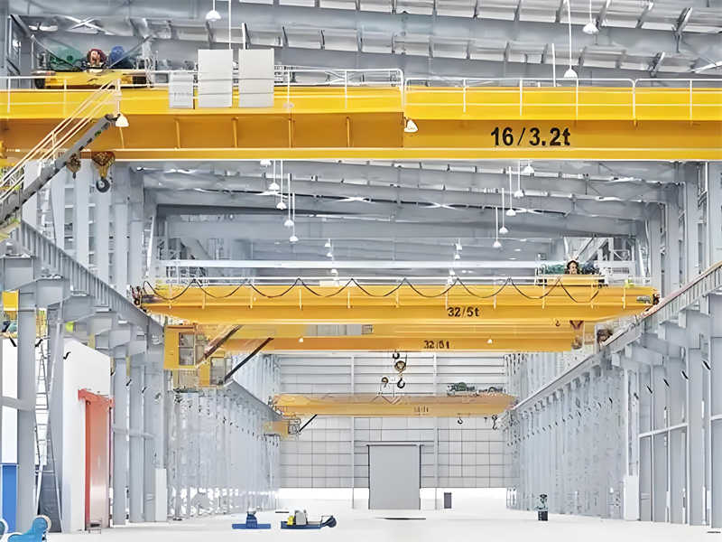
A bridge crane, also known as an overhead crane or traveling crane, is a type of overhead crane with a bridge running on elevated tracks. It is widely used in factories, mines, and other locations for handling large parts and heavy equipment. As a medium-sized lifting equipment, the 32/5t electric double-girder bridge crane features a main and auxiliary hoist mechanism, capable of meeting lifting requirements of varying weights and playing a vital role in industrial production.
As a core component of a bridge crane, the performance of the trolley mechanism directly impacts the crane’s operating efficiency, positioning accuracy, and operational safety. An excellent trolley mechanism design should achieve smooth starting, accurate braking, and reliable operation, while also ensuring high energy efficiency and a long service life.
Design Task Overview
This design task involves the trolley mechanism for a 32/5t electric double-girder overhead crane. Key technical parameters are as follows:
Lifting capacity: Main hook 32t / Auxiliary hook 5t
Working class: M5
Operating speed: 45m/min
Track gauge: 2500mm
Wheelbase: 2700mm (reference value)
Trolley deadweight: Approximately 11.5t
Lifting height: Main hook 16m / Auxiliary hook 18m
Overall Design of the Trolley Operating Mechanism
Structural Composition and Operating Principle
The trolley operating mechanism of a 32/5t electric double-girder overhead crane primarily consists of the following components:
Drive Unit: Includes the motor, reducer, brake, and coupling.
Traveling Mechanism: Includes the wheel assembly, wheel axle, and bearing assembly.
Transmission System: Includes the drive shaft, coupling, and open gears.
Frame Structure: The metal structure that supports and connects the various components.
Safety Devices: Includes buffers, limit switches, and derailment prevention devices.
Operating Principle: The motor transmits power to the reducer via the coupling. After deceleration and torque amplification, the power is distributed to the drive wheels on both sides via the drive shaft. Ultimately, friction between the wheels and the rails enables the trolley to move longitudinally along the bridge’s main girder rails.
Overall Layout
Based on the specifications and operational requirements of the 32/5t crane, the trolley mechanism utilizes a centralized drive system. The specific layout is as follows:
Drive Method: A centrally driven electric motor on one side is used, with a drive shaft providing synchronized rotation of the driving wheels on both sides.
Wheel Arrangement: A four-wheel structure, with two driving wheels and two driven wheels.
Braking System: A normally closed brake is installed on the high-speed shaft to ensure automatic braking in the event of a power outage.
Select double-rim cast steel wheels with a diameter of Φ500 mm and QU70 track. The allowable wheel pressure of 150 kN > 117.5 kN meets the requirements.
Fatigue Strength Verification:
Contact stress calculated according to ISO standards:
σH = 0.418 × √(Pmax × E/(b × R)), where b = 70 mm (rail top width), R = 250 mm (wheel radius), and E = 2.1 × 10⁵ MPa:
To connect the motor and reducer, select the GICL3 drum gear coupling. Its permissible torque of 1600 N·m (> 9550 × 11/953 = 110 N·m) meets the requirements.
Low-Speed Shaft Coupling:
To connect the reducer and drive shaft, select the GICL6 drum gear coupling. Its permissible torque of 6300 N·m (> 5500 N·m) meets the requirements.
Protection Functions: Multiple protections, including overcurrent, overvoltage, undervoltage, overspeed, and limit switches
Speed Curve Planning
Optimized starting and braking speed curves to reduce shock:
Startup Time: 4 seconds, acceleration 0.1875 m/s²
Braking Time: 3 seconds, deceleration 0.25 m/s²
S-shaped Curve: S-shaped speed changes are used during acceleration and deceleration to reduce shock
3D Modeling and Engineering Drawings
Based on the above design, a complete set of engineering drawings was completed using CAD software, including:
Trolley running mechanism assembly drawing: Demonstrates the overall layout and assembly relationships
Component assembly drawings: Drive unit, wheel assembly, drive shaft, etc.
Parts drawings: Key components such as wheels, shafts, gear couplings, etc.
3D Model: Used for interference checking and motion simulation
Table: List of main engineering drawings
Pattern Name
Map Sheet
Main content
Assembly drawing of trolley running mechanism
A0
Overall layout, main dimensions
Drive assembly drawing
A1
Motor, reducer, and brake assembly
Wheel assembly drawing
A2
Assembly relationship of wheels, bearings and shafts
Drive shaft parts drawing
A3
Shaft structure, dimensional tolerance, and technical requirements
Welding diagram of trolley frame
A1
Structural dimensions, welding symbols, and process requirements
Conclusion
This design completes the comprehensive design of the trolley operating mechanism for a 32/5t electric double-girder overhead crane. Through theoretical calculations and verification, the main conclusions are as follows:
The trolley operating mechanism utilizes a centralized drive system, using a YZR160M1-6 electric motor (11kW) and a ZQ-350 reducer. The operating speed is 42.6 m/min, meeting the design requirement of 45 ± 10% m/min.
Key components such as the wheel assembly (Φ500mm double-flange cast steel wheel), drive shaft (Φ90mm 42CrMo), and coupling have all passed strength verification and meet the fatigue life requirements for the M5 duty class.
The use of variable frequency speed control and S-shaped speed curve planning ensures smooth starting and braking, with a maximum acceleration of 0.1875 m/s² and a deceleration of 0.25 m/s², effectively reducing impact loads.
Safety devices, including buffers, limit switches, and anti-derailment devices, meet the safety requirements of crane design specifications.
The 3D model and engineering drawings fully convey the design intent and can be used for actual manufacturing and assembly.
This design comprehensively considers performance, safety, and economic factors, providing a reference for the design of similar crane trolley operating mechanisms. Future work will allow for further optimization of the lightweight design, exploration of new transmission methods and intelligent control strategies, and advancement of the operating mechanism’s technical capabilities.
Contact our crane specialists
Send us a message and we will get back to you as soon as possible.