Home → News → Comprehensive Structural Design Scheme for 50T/10T Bridge Cranes
Comprehensive Structural Design Scheme for 50T/10T Bridge Cranes
Design Overview
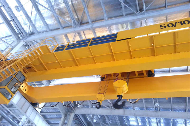
50t/10t bridge cranes are heavy-duty lifting equipment widely used in industrial production, primarily for heavy load handling, loading and unloading machine tools, and assembly line hoisting in factories, workshops, warehouses, and other locations. This design focuses on a QD50/10t bridge crane, primarily encompassing the design of the trolley running mechanism, trolley bridge, and trolley auxiliary hoist mechanism. With the rapid development of my country’s manufacturing industry, these small and medium-sized bridge cranes are increasingly widely used in various factories, becoming an indispensable key piece of equipment in production line logistics systems.
This design will adhere to crane design specifications and comprehensively consider various requirements, including structural strength, static stiffness, and dynamic stiffness, to ensure safe and stable operation of the crane under both fully loaded and unloaded conditions. The design process will include parameter determination, structural design, component selection, and strength verification, ultimately resulting in a complete structural design solution for a bridge crane that meets the requirements of a 50-ton main hoist and a 10-ton auxiliary hoist.
Main Technical Parameter Design
The technical parameters of a bridge crane are the core design criteria, directly determining the equipment’s performance and application range. According to industry standards and actual needs, the main technical parameters of 50T/10T bridge crane are designed as follows:
Lifting Capacity:
Main hoist rated load: 50 tons
Auxiliary hoist rated load: 10 tons
This dual-hook configuration meets lifting requirements for materials of varying weights, improving work efficiency.
Span Design:
Standard span range: 16.5m-31.5m (depending on actual factory requirements).
The main beam length must be greater than the span, with a certain extension at each end.
Lifting Height:
Main hook lifting height: 12m-16m (depending on user requirements).
Auxiliary hook lifting height: 14m-18m (typically 2m higher than the main hook).
Operating Speed:
Main hoist speed: 3.5-7.5m/min (adjusted depending on work level).
Auxiliary hoist speed: 7-14m/min (typically twice the main hook speed).
Trolley operating speed: 20-50m/min.
Trolley operating speed: 10-20m/min.
Operating Class:
Operating Class: A5-A6 (Medium-duty)
Main hoist mechanism: M5
Auxiliary hoist mechanism: M4
Trolley operating mechanism: M4
Trolley operating mechanism: M4
Wheel load parameters:
Maximum wheel load: ≤28t (calculated based on the specific span)
These technical parameters will serve as the basis for subsequent structural design and component selection. The actual design will require appropriate adjustments based on the user’s specific needs and installation environment.
Bridge Structure Design
The bridge is the core load-bearing structure of a bridge crane, and its design directly impacts the safety, reliability, and performance of the entire crane. The bridge of a 50T/10T bridge crane utilizes a double-girder, center-track box-type structure, consisting of two main beams, two end beams, a walkway, and guardrails.
Main Girder Design
Structural Selection:
A skewed box girder structure is used, with the track located at the center of the main girder’s upper flange.
The box girder consists of upper and lower decks, a web, and several longitudinal stiffeners.
Transverse diaphragms are installed within the main girder, spaced approximately 1.5-2 meters apart, to enhance local stability.
Cross-Sectional Dimensions:
Beam Height: H = (1/14-1/18) L (L = span), preferably 1600-1800 mm.
Web Height: 2 times the beam height (less than the upper deck thickness), approximately 1550-1750 mm.
Web Thickness: δ = 10-14 mm (determined based on strength calculations).
Upper deck width: 600-800 mm, thickness 20-30 mm.
Lower deck width: 500-700 mm, thickness 16-25 mm. mm
Main Beam Strength Calculation:
Vertical Load Calculation: Includes trolley weight, hoist weight, and main beam weight.
Horizontal Load Calculation: Considers inertia and lateral forces due to skew operation.
Strength Verification: Combined normal and shear stress calculations are performed according to GB/T3811-2008.
Main Beam Stiffness Calculation:
Static Stiffness: Vertical static deflection at midspan should meet the requirement of f ≤ L/800 to L/1000.
Dynamic Stiffness: The first-order natural frequency of the main beam should be no less than 2 Hz.
Horizontal Stiffness: Horizontal displacement at midspan should be no greater than L/2000.
Main Beam Camber Design:
Precast Camber: Designed based on L (0.9/1000-1.4/1000).
Camber Curve: Use a quadratic parabola or sine curve.
Consider the effects of main beam and trolley weight on deflection.
End Beam Design
Structural Form:
Box-type structure, rigidly connected to the main beam to form an integral frame.
End beams are bolted in the middle for easy transportation and installation.
Cross-sectional Dimensions:
Height: 600-800mm (coordinated with the main beam end height)
Width: 400-600mm (considering space for wheel assembly installation)
Web Thickness: 10-12mm
Cover Thickness: 16-20mm
Connection Design:
Main beam and end beams are connected using high-strength bolts or welding.
The new design uses a flexible hinged structure with one end fixed and the other pinned, allowing the main beam to deform under load.
Local strength verification is required at the connection points.
End Beam Accessories:
Buffers (usually polyurethane or rubber)
Travel limit switches and safety bars
Equipped with a grounding protection device
Walkway and Accessory Structures
Walkway Design:
Located outside the main beam, with a width of 800-1000mm.
Use expanded metal or patterned steel for decking.
Install diagonal braces underneath the walkway to enhance overall stability.
Guardrail Installation:
Guardrails are installed on both sides of the walkway, with a height of ≥1050mm.
The spacing between railing posts is ≤1500mm.
A horizontal bar is installed in the middle, with a baseboard at the bottom.
Electrical Equipment Installation:
Electrical equipment such as resistors and control cabinets are installed on the walkway.
Consider heat dissipation and maintenance space for the equipment.
After the bridge structure design is completed, a comprehensive finite element analysis is performed to verify that the strength, rigidity, and stability meet the requirements under various operating conditions. Optimization and adjustments will be made based on the analysis results.
Gantry Mechanism Design
The gantry mechanism is a key component that drives the crane longitudinally along the factory rails. Its design quality directly impacts the crane’s operational performance and safety. The gantry mechanism of 50T/10T bridge cranes utilizes a separate drive system, with each driving wheel driven by an independent drive unit.
Overall Layout
Drive Options:
Two independent drive units are used, one on each end beam.
Each drive unit includes a motor, brake, reducer, coupling, and wheel assembly.
Wheel Assembly Configuration:
Two wheels are installed on each end beam, for a total of four wheels.
All wheels can be driven (four-wheel drive) or partially driven (two-wheel drive).
For 50T/10T cranes, a full wheel drive system is recommended.
Track Options:
QU70 or QU80 crane-specific rails are used.
Track Installation must ensure track gauge tolerance and levelness requirements.
Couplings must be calibrated for torque and permissible speed.
Drivetrain Layout
Traditional Layout:
Motor → Brake → Reducer → Coupling → Wheel Assembly
Each component is connected via a coupling.
A separate bracket and base are required.
Three-in-One Drive Unit:
A three-in-one drive unit integrates the motor, brake, and reducer.
Compact design, easy installation, and simplified maintenance.
Particularly suitable for trolley travel mechanisms.
Safety Device Configuration:
Travel limit switches and buffers installed.
Track sweepers and track cleaning devices installed.
Anti-collision devices installed (when multiple cranes share the same track).
Balance Beam Structure Design (if applicable).
For large-tonnage cranes or applications with strict wheel load restrictions, a balance beam structure can be used to balance wheel loads.
Balance Beam Structure Types:
Single or double balance beams.
Hinge point design must ensure even load distribution.
Balance Beam Optimization:
Optimize cross-sectional shape through finite element analysis.
Reduce weight while maintaining rigidity.
Use self-lubricating bearings at hinge points.
After the trolley travel mechanism design is completed, calculations for running resistance, starting time, and braking coasting distance are performed to ensure that all performance indicators meet operational requirements.
Hoist Trolley Design
The trolley is the component of a bridge crane that directly performs lifting tasks. The trolley design for a 50T/10T bridge crane must meet both the main lift capacity of 50 tons and the auxiliary lift capacity of 10 tons. The trolley structure primarily consists of the trolley frame, hoisting mechanism, and operating mechanism.
Trolley Frame Design
Structural Form:
A box-type structure made of welded steel plates, consisting of two longitudinal beams and several transverse beams.
The longitudinal beams utilize a box-shaped cross section, while the transverse beams utilize I-beams or box beams depending on the layout.
Strength Analysis:
The calculated load includes the rated lifting capacity, the trolley’s deadweight, and the dynamic load factor.
Consider the most unfavorable operating conditions when the main and auxiliary hooks operate simultaneously.
Perform strength checks in both vertical and horizontal directions.
Stiffness Requirements:
The trolley frame’s deflection under rated load must not exceed 1/1000 of the span.
Torsional deformation must be kept within the allowable range.
Accessory Requirements:
Safety devices such as railings, access platforms, and pulley guards must be installed.
Consider the installation locations of the wire rope anti-slip device and rope guide.
Main Hoisting Mechanism Design (50 tons)
Overall Layout:
A closed transmission system is used, with the motor connected to the reducer via a coupling.
The reducer output shaft drives the drum, which raises and lowers the hook via a wire rope and pulley system.
Wire Rope Selection:
Calculate the maximum working tension of the wire rope: Smax = Q/(a·η).
Q = rated lifting capacity, a = pulley system ratio, η = pulley system efficiency.
Select 6×36WS+IWR wire rope, diameter ≥ 22mm.
Safety factor n ≥ 5.6.
Pulley System Design:
Use a double pulley system with a ratio m = 4-6.
Pulley diameter D ≥ 25d (d is the wire rope diameter).
Pulley material: ZG270-500 cast steel.
Drum Design:
Drum diameter D ≥ 20d.
Length L Calculate based on the lifting height and wire rope diameter.
Use single-layer winding with spiral grooves at both ends.
Use HT200 or Q345B as the material.
Motor Selection:
Static Power Calculation: P = (Q·v) / (6120η)
v = lifting speed, η = total mechanism efficiency.
Use a YZR series motor with approximately 45-55kW.
Standard duty cycle: S3, 40% duty cycle.
Brake Selection:
Braking torque should meet the following requirements: Mz ≥ Kz·Mj.
Kz = safety factor (≥1.75), Mj = static torque.
Use a YWZ hydraulic push rod brake.
Reducer Selection:
Transmission Ratio Calculation: i = n1/n2 = n1/(v·a/(πD)).
Use a QJS or QJR crane-specific reducer.
Auxiliary Hoist Design (10-ton)
The auxiliary hoist design is similar to the main hoist, but with different parameters:
Wire Rope Selection:
Diameter ≥ 14mm, 6×37+FC
Safety Factor n ≥ 5.6
Pulley Block Design:
Ratio m = 2-4
Pulley Diameter D ≥ 20d
Motor Selection:
Power approximately 15-22kW; Higher speed for increased lifting speed
Reducer Selection:
Relatively small transmission ratio to accommodate higher speeds
Trolley Operating Mechanism Design
Drive Mode:
Centralized or separate drives are recommended.
For 50t/10t trolleys, separate drives are recommended.
Motor Selection:
Power approximately 3.5-5.5kW.
Speed determined by operating speed.
Wheel Assembly Design:
Wheel diameter Φ250-Φ350mm.
Double-flange wheels are used.
Safety Devices:
Travel limit switches and buffers are provided.
Anti-derailment protection devices are installed.
Trolley design requires comprehensive consideration of the layout of the main and auxiliary lifting mechanisms, maintenance space, and weight balance. Optimization and verification are conducted through 3D modeling and finite element analysis.
Electrical Control System Design
The electrical control system for a 50T/10T overhead crane is a critical component for ensuring the coordinated and safe operation of all mechanisms. The design must meet the crane’s electrical traction requirements to ensure reliable and safe operation.
Power Supply and Distribution System
Power Supply Method:
Powered by busbar (main busbar) or cable drum.
The main busbar is located along one side of the plant track, with a voltage of 380V AC, 50Hz.
The trolley conduction system uses an auxiliary busbar or cable trolley system.
Power Distribution System Design:
A main disconnector and short-circuit protection device are provided.
Each motor has an independent circuit breaker.
An emergency power-off switch (mushroom-head pushbutton) is provided.
Grounding Protection:
A reliable grounding system is provided for the entire machine.
Grounding resistance ≤ 4Ω.
Track grounding distance ≤ 30m.
Drive Control System
Hoisting Mechanism Control:
Use rotor series resistance speed control or variable frequency speed control.
Variable frequency speed control offers energy-saving, stable, and precise control.
Dual protection for rising limits (weight limit and screw limit) is provided.
Travel Mechanism Control:
Both the trolley and carriage travel mechanisms can use cam controllers or variable frequency control.
Variable frequency control ensures smooth starting and
Contact our crane specialists
Send us a message and we will get back to you as soon as possible.