Home → News → Electrical design scheme for (15+15)t×22m×24m-A6 class material box loading double beam double trolley bridge crane
Electrical design scheme for (15+15)t×22m×24m-A6 class material box loading double beam double trolley bridge crane
I. Design Overview
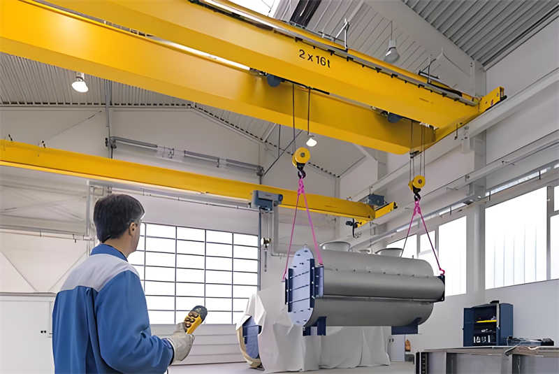
This electrical design is for a (15+15)t × 22m × 24m A6-class, double-girder, dual-trolley bridge crane for bin loading. This heavy-duty industrial crane features a double-girder structure, dual trolley configuration, and an A6 duty cycle, making it suitable for frequent bin loading operations.
Applicable Environment: Industrial Plants, Bin Loading Operations
The A6 duty cycle indicates that this crane is suitable for moderately busy operations, with high frequency and load requirements. The dual trolley design enables simultaneous or independent operation, improving material handling efficiency.
II. Overall Electrical System Design
1. System Composition
The electrical system of a double-girder, dual-trolley bridge crane primarily includes the following subsystems:
Main power supply system
Trolley operation control system
Trolley operation control system (including two independent systems)
Hoisting mechanism control system (two each for the main and auxiliary hoists)
Safety protection system
Lighting and auxiliary circuit system
Operation and signaling system
2. Electrical Control Scheme
Based on the A6 operating level and the requirements for dual-trolley coordinated operation, the following control scheme is recommended:
Main Controller: PLC (Programmable Logic Controller) serves as the core control unit, enabling coordinated control and logical interlocking of various mechanisms
Drive Mode: Variable frequency speed control for smooth starting and precise stopping
Operation Mode: Cab control + ground remote control (optional), with a linkage control console in the cab
3. Power System Design
Main power supply: Three-phase AC 380V, 50Hz, supplied via a safety busbar or cable reel
Power distribution system: The main distribution cabinet is equipped with a main power circuit breaker, short-circuit protection, and overload protection
Control power: An isolation transformer provides 220V control power and 24V safety voltage
III. Selection of Main Electrical Components
1. Drive Motor Selection
Based on the A6 duty class and (15+15)t load requirements:
Hoisting Motors: Two YZP series metallurgical hoist variable frequency motors, each with approximately 22kW power, insulation class F, IP54 protection class
Trolley Running Motors: Four (two per trolley) YZR series wound rotor motors, approximately 3.7kW power
Trolley Running Motors: Four YZR series motors, approximately 7.5kW power
2. Frequency Converter Selection
A dedicated frequency converter for hoisting is used, with the following features:
The hoisting mechanism frequency converter features torque verification and hook slip prevention functions
The running mechanism frequency converter features brake control and smooth speed regulation functions
Recommended Brands: Siemens, ABB, or high-quality domestic brands
3. Control Electronics Selection
PLC: Siemens S7-1200 or equivalent controller with expansion modules
Contactors and Relays: Schneider or ABB, meeting A6 duty cycle operating frequency
Limit Switches: Heavy-duty mechanical limit switches, IP65 or higher
4. Safety Protection Devices
Electrical Protection: Overcurrent, short circuit, phase loss, overvoltage, and undervoltage protection
Emergency Protection: Emergency stop button, anti-collision device (between the two trolleys)
IV. Control System Detailed Design
1. Main Circuit Design
The main circuit utilizes a hybrid control scheme combining traditional relays and contactors with a frequency converter:
Main power circuit breaker → main contactor → power distribution to each mechanism
The hoisting mechanism utilizes a frequency converter + brake unit + brake resistor solution
The operating mechanism utilizes frequency converter control with resistor speed regulation
2. Control Circuit Design
The control circuit, with a PLC as its core, implements the following functions:
Start, stop, and speed regulation control for each mechanism
Switching between dual-trolley linkage and independent control modes
Safety interlocks (such as door interlocks and limit interlocks)
Fault diagnosis and alarms
3. Dual-trolley Coordinated Control
Specialized control logic is designed for dual trolleys:
Independent control mode: Each trolley can be operated independently
Synchronous control mode: Both trolleys operate synchronously to maintain load balance
Anti-collision control: Automatically decelerates when the two trolleys approach
4. Operator Interface Design
The operator’s cab is equipped with a linkage control console, including a master controller, buttons, and indicator lights.
The display panel displays lift capacity, operating status, fault information, etc.
Optional wireless remote control system
V. Electrical Layout and Wiring Design
1. Electrical Equipment Layout
Main distribution cabinet: Installed on one side of the bridge, near the trolley power supply point
Resistor box: Installed in a well-ventilated location above the bridge
Driver’s cab control box: Integrated into the driver’s console
Trolley electrical box: Independently configured for each trolley
2. Wiring Design
Main power cables use heavy-duty rubber-sheathed cable or insulated conductors
Control cables use shielded cable to prevent interference
Trolley power supply uses safety busbars or cable reels
Trolley power supply uses flat cables or cable pulleys
VI. Safety Protection System Design
1. Electrical Protection
Short-circuit protection: Dual protection with circuit breakers and fuses
Overload protection: Thermal relays and electronic overload protection
Phase loss protection: Dedicated phase loss protection relay
2. Mechanical safety protection
Lift height limit: Dual limiters (operating limit and emergency limit)
Travel limiters: Limit switches installed at both ends of the trolley and trolley
Overload limiter: Electronic overload limiter with an accuracy of ±3%
Windbreak: Rail clamps or anchors (for outdoor use)
3. Interlock Protection
Door Interlock: All access doors and railing doors are equipped with interlock switches
Emergency Stop: Emergency stop buttons are installed at each operating point
Zero Position Protection: The controller cannot be started if it is not in the zero position
VII. Lighting and Auxiliary Circuits
1. Lighting System
Bridge Lighting: LED floodlights, illuminating the work area
Driver’s Cab Lighting: Shock-resistant lamps with adjustable brightness
Maintenance Lighting: Safe voltage (36V or 24V) lighting sockets
2. Auxiliary Circuits
Electric bell or buzzer: Pre-operation warning
Maintenance sockets: Several 220V and 36V sockets
Heating and dehumidification system: Inside the driver’s cab and electrical cabinet (as required by the environment)
VIII. Installation and Commissioning Key Points
1. Electrical Installation
Strictly follow the electrical drawings, paying attention to wire number markings.
Lay power and control wires separately to avoid interference.
All electrical equipment must be reliably grounded, with a ground resistance of ≤4Ω.
2. Commissioning Process
Single-unit commissioning: Power-on test of each mechanism individually
No-load coordinated commissioning: Coordinated operation test of each mechanism
Loaded commissioning: Gradually load the device to the rated load
Safety device testing: Verify all protective functions
3. Commissioning Key Points
Inverter parameter optimization: Adjust parameters based on actual load
Brake adjustment: Ensure reliable braking without slippage
Limit switch adjustment: Ensure accurate triggering
IX. Maintenance and Troubleshooting
1. Routine Maintenance
Regularly check the tightness of electrical connections
Clean electrical equipment and maintain good ventilation
Check cables and busbars for wear
2. Common Troubleshooting
Motor Overheating: Check the load, ventilation, or bearing condition
Brake Failure: Check brake pad wear and electrical controls
Limit Failure: Check switch position and wiring
X. Design Output Files
Upon completion of this electrical design, the following technical documents will be provided:
Electrical Schematics (Main Circuit, Control Circuit, Lighting Circuit, etc.)
Electrical Equipment Layout
Electrical Component List
PLC Program Files
Frequency Converter Parameter Setting Sheet
Installation and Commissioning Outline
Operation and Maintenance Manual
Conclusion
This design addresses the specific requirements of a (15+15)t×22m×24m) A6-class, double-girder, dual-trolley bridge crane for bin loading. It utilizes PLC control combined with variable frequency speed regulation technology to achieve coordinated operation of the dual trolleys and safe and reliable operation. The design fully considers the frequent use of the A6 duty cycle, selecting high-reliability electrical components and implementing multiple safety features to ensure efficient and safe operation of the crane during bin loading operations.
Contact our crane specialists
Send us a message and we will get back to you as soon as possible.