This design presents a comprehensive analysis of the hoisting mechanism for a 32/5-ton double-girder bridge crane, encompassing key aspects such as transmission scheme determination, key component selection and calculation, mechanism layout optimization, and safety verification. As a key piece of equipment for modern industrial material handling, the design of the hoisting mechanism of a bridge crane directly impacts the overall performance, safety, reliability, and economic efficiency of the entire machine. Based on crane design specifications and incorporating the technical parameters of a 32-ton main hook and a 5-ton auxiliary hook, this article details the hoisting mechanism design process, including key aspects such as wire rope selection, pulley block configuration, drum design, motor and reducer matching, and brake system calculation. Furthermore, corresponding verification methods are provided, ultimately resulting in an efficient, safe, and reliable hoisting mechanism design that meets M5 duty class requirements.
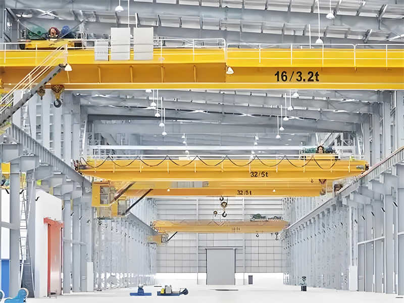
The 32/5-ton bridge crane is a heavy-duty lifting device with stable performance and high efficiency. It is widely used for heavy lifting operations in machinery manufacturing, the steel industry, power equipment installation, and large-scale warehouses. This design project requires the development of a safe and reliable hoisting mechanism that complies with national standards. Key technical parameters, determined based on project requirements, are as follows: the rated lifting capacity of the main hook is 32 tons, the auxiliary hook is 5 tons; the main hook’s lifting height is 16 meters, the auxiliary hook’s is 18 meters; the main hook’s lifting speed is 7.51 m/min (0.125 m/s), the auxiliary hook’s is 19.5 m/min (0.325 m/s); and the mechanism’s operating class is M5 (heavy duty according to ISO 4301). These basic parameters will serve as input and verification criteria for all subsequent design calculations.
Operating class is a crucial concept in crane design. M5 indicates that the hoisting mechanism will be used in moderately busy operations, with a total design life of no less than 3.2 × 10^5 operating cycles. This class requires full consideration of fatigue strength and durability during design. As the core component of a crane, the hoisting mechanism’s performance directly determines the reliability and efficiency of the entire crane. Modern bridge crane hoisting mechanisms generally adopt a modular design concept, integrating and optimizing the power, transmission, and control systems for easier maintenance and improved space utilization.
The following basic principles must be adhered to during the design process: First, safety: reliable operation under all operating conditions must be ensured, and multiple safety protection devices must be installed. Second, economy: optimizing configuration and reducing manufacturing costs while meeting performance requirements. Third, ease of maintenance: components should be arranged for easy inspection and replacement. Finally, advancement: appropriately incorporating proven new technologies and processes to enhance performance. Based on these principles, this design will proceed in stages, including transmission design, component selection and calculation, structural layout optimization, and performance verification.
It is worth noting that 32/5-ton bridge cranes are large-capacity lifting equipment, with their trolleys weighing approximately 11.5 tons. The impact of this weight on overall structural strength must be fully considered during the design. At the same time, with the development of modern transmission technology, “three-in-one” transmission devices (drive units that integrate electric motors, brakes, and speed reducers) are becoming increasingly widely used in lifting machinery. This compact, lightweight, and easy-to-assemble drive method is particularly suitable for small and medium-sized cranes. However, in the design of this 32/5-ton high-lift capacity, considering the reliability and maintenance convenience of the traditional form, a split design is still adopted.
The hoisting mechanism drive design is a core component of crane design. A suitable drive solution not only meets basic performance requirements but also improves energy efficiency, reduces maintenance costs, and extends service life. Based on the parameters and operational requirements of 32/5-ton bridge cranes, this design utilizes a typical dual-drum independent drive arrangement. The main hook (32t) and auxiliary hook (5t) are each controlled by two independent drive systems, sharing the trolley structure but without interfering with each other. This arrangement maximizes the optimal performance of each hook and avoids mutual interference between the large and small hooks.
The main hoisting mechanism drive system utilizes a traditional motor-coupling-brake-reducer-drum assembly layout. The motor is connected to the reducer via a high-speed shaft coupling, and a block brake is installed at the motor’s rear end, forming a typical closed drive system. The reducer’s low-speed output shaft is connected to the drum via a gear coupling, creating a stable torque transmission path. This arrangement offers simple structure, ease of maintenance, and ample clearance between components, which is consistent with the operational characteristics of heavy-duty cranes. The auxiliary hoist mechanism uses a similar layout, but due to the higher speed and smaller load, the components are smaller. However, they must also meet the strength requirements of the M5 operating class.
The pulley block design significantly impacts the overall size and efficiency of the hoist mechanism. In this design, the main hook utilizes a double pulley block with a multiplier of 6, meaning 12 wire rope branches. This arrangement effectively reduces the tension on a single wire rope, extending its service life while also reducing drum size and making the structure more compact. Due to the lower lifting capacity but higher speed requirements, the auxiliary hook utilizes a four-branch structure with a multiplier of 2, maximizing the lifting speed while meeting the load requirements. The pulley diameter is selected strictly according to the principle of D ≥ (h-1) d, where h is the ratio of the pulley diameter to the wire rope diameter (set to 28 based on the operating class) and d is the wire rope diameter to ensure the bending fatigue life of the wire rope.
The hook block is the direct load-bearing component of the hoist mechanism, making its selection particularly important. The main hook is a 32-ton forged hook made of high-quality low-carbon alloy steel, heat-treated, and precision-machined. The hook surface undergoes magnetic particle inspection to ensure it is free of cracks and other defects. The hook assembly is supported by a thrust bearing, ensuring flexible rotation and reducing torsional stress on the wire rope. All pulley bearings are heavy-duty roller bearings, grease-lubricated, and sealed to prevent dust intrusion. The auxiliary hook assembly utilizes a similar structure with a rated load of 5 tons, complementing the main hook to meet the lifting needs of materials of varying weights.
To ensure the safety of the hoisting mechanism, multiple protective devices are integrated into the design: an overload limiter prevents overloading, issuing a warning signal when the load reaches 90% of the rated load and automatically cutting off the lifting power at 105%. A height limiter employs both a weight and a screw to prevent the hook from hitting the top. A lowering depth limiter automatically stops the hook at its lowest position, preventing excessive slack in the wire rope. In addition, the electrical system incorporates safety features such as zero-position protection, an emergency stop switch, and phase sequence protection, forming a complete protection system that complies with the requirements of GB6067, “Safety Regulations for Cranes.”
The transmission layout also considers ease of maintenance. This design incorporates an inspection platform on one side of the drum, with all lubrication points easily accessible. The reducer is equipped with an oil gauge and drain port, and the brake adjustment mechanism is exposed for easy clearance adjustment. Major components, such as the motor and reducer, utilize standard mounting interfaces, allowing for independent replacement without disassembling other components, significantly improving maintenance efficiency. While this user-friendly design increases initial design complexity, it is crucial for long-term maintenance and is particularly well-suited for the frequent use conditions of the M5 operating level.
As the most critical load-bearing component in the hoisting mechanism, the wire rope’s proper selection directly impacts the crane’s safety and reliability. Based on the operating characteristics of a 32/5-ton bridge crane, the main hook hoisting mechanism’s wire rope must withstand a maximum load of 32 tons (the actual load is even greater after considering the dynamic load factor). Therefore, precise calculation and appropriate selection are essential. The basic requirements for wire rope selection are: while meeting strength requirements, it must also possess excellent flexibility, wear resistance, and fatigue resistance to withstand repeated bending and winding.
The calculation process for selecting the main hook wire rope is as follows: First, determine the wire rope’s maximum static operating tension, Smax. Considering the pulley block efficiency η (assuming 0.98) and the multiplier m (assuming 6), Smax = Q/(m·η) = 32000 × 9.81/(12 × 0.98) ≈ 26.7 kN, where 12 is the actual number of load-bearing legs (for a double pulley block, a multiplier of 6 corresponds to 12 legs). Considering the dynamic load generated when the hoisting mechanism is working, the dynamic load coefficient φ2 is introduced (taken as 1.15 for the M5 working level), and the calculated tension S’=φ2×Smax=1.15×26.7≈30.7kN. According to the standard GB/T8918-2006 “Steel Wire Ropes for Important Purposes”, the minimum breaking tension F0 of the selected wire rope should meet F0≥S’×n, where n is the safety factor. For the M5 working level, it is taken as 5.5, so F0≥30.7×5.5≈168.8kN. Based on this, the 6W(19)-22-1570 type wire rope is selected, with a nominal tensile strength of 1570MPa and a minimum breaking tension of 183kN (fiber core) or 198kN (steel core), which fully meets the requirements.
The calculation method for the auxiliary hook wire rope is similar, but due to the smaller lifting capacity and higher speed, the factors considered are slightly different. The rated lifting capacity of the auxiliary hook is 5 tons, the pulley group ratio is 2 (number of branches is 4), and the pulley group efficiency is 0.96, then Smax=5000×9.81/(4×0.96)≈12.8kN. The dynamic load coefficient is also taken as 1.15, and the calculated tension S’=1.15×12.8≈14.7kN. The safety factor is also taken as 5.5, and the required minimum breaking tension F0≥14.7×5.5≈80.9kN. The 6W(19)-14-1570 type steel wire rope is selected, with a minimum breaking tension of 89.5kN (fiber core), which meets the use requirements. This steel wire rope structure is 6 strands and 19 wires, with line contact, large metal cross-section area, good wear resistance, and is particularly suitable for crane hoisting mechanisms with frequent work.
The pulley is the support and guide component of the wire rope, and its design must be well matched with the wire rope to avoid premature wear. Key pulley design parameters include pulley diameter D, rope groove radius R, and pulley width B. Based on the principle of D ≥ (h – 1) d, for the main hook pulley, h is set to 28, and for a wire rope diameter d = 22 mm, D ≥ (28 – 1) × 22 = 594 mm. The actual D = 630 mm is used, meeting both regulatory requirements and common pulley dimensions. The rope groove radius R is set to (0.53-0.56) d = 11.7-12.3 mm, with an actual R = 12 mm to ensure adequate rope clearance without excessive constriction. The pulley is made of cast steel ZG270-500, and the rope groove is surface-hardened to HRC 45-50, with a depth of 2-3 mm to enhance wear resistance.
Pulley bearing selection is also a key design consideration. The main hook pulley utilizes a double-row spherical roller bearing, model 22220C/W33, with a rated dynamic load of up to 245 kN, fully capable of withstanding the radial load of the wire rope. This bearing features a self-aligning function to compensate for installation errors, and its excellent sealing performance makes it suitable for the dusty operating environment of cranes. Bearing life calculations are based on ISO 281 standards, considering an equivalent dynamic load P = 1.1 × Smax (1.1 being the nonuniformity factor) = 1.1 × 26.7 ≈ 29.4 kN. The rated life L10 = (C/P)^(10/3) × 10^6 revolutions = (245/29.4)^(10/3) × 10^6 ≈ 3.2 × 10^8 revolutions. Based on an average operating speed of 50 rpm, this translates to approximately 100,000 hours, far exceeding the crane’s design lifespan and ensuring that replacement is not required during its lifetime.
The pulley block’s structural design also prioritizes lightweighting and maintainability. This design utilizes a spoke-plate pulley structure to reduce weight while ensuring sufficient strength. Each pulley features a separate bearing seat and lubrication channel for easy maintenance and replacement. The pulley assembly housing is equipped with an inspection window and grease nipple, allowing for inspection of the wire rope condition and relubrication without disassembly. The main hook pulley assembly consists of six movable and six fixed pulleys, symmetrically arranged to balance wire rope tension. The auxiliary hook pulley assembly consists of one movable and one fixed pulley, resulting in a simple and compact structure. All pulleys are equipped with anti-rope skipping devices to prevent accidents caused by the wire rope slipping out of the groove.
The wire rope securing method is also a key design consideration. This design uses a pressure plate to secure the wire rope end to the drum. This method is simple, reliable, and easy to inspect and replace. Three clamping bolts are installed at the fixing point to ensure sufficient clamping force. According to GB/T5972, the strength of the fixing point must be no less than 80% of the minimum breaking strength of the wire rope. This design fully meets this requirement by increasing the thickness of the drum end and using high-strength bolts. In addition, at least two safety rings should be kept on the drum to prevent the wire rope from accidentally loosening. This is also a mandatory requirement in the crane design specifications.
The drum is a key component in the hoisting mechanism, used for winding and storing wire rope. Its design quality directly impacts the crane’s safety and reliability. In the design of the hoisting mechanism of a 32/5-ton overhead crane, the drum must not only withstand the immense tensile forces of the wire rope but also withstand repeated bending and compressive stresses. Therefore, precise design and rigorous verification are essential. Drum design primarily involves selecting the structural form, determining basic dimensions, selecting materials, and calculating strength.
The design and calculation process for the main hook drum is as follows: First, determine the basic parameters of the drum, including diameter, length, groove type, and wall thickness. According to crane design specifications, the nominal drum diameter D should satisfy D ≥ (h-1)d, where h is a coefficient related to the operating class (20 for M5 class) and d is the wire rope diameter (22 mm). Therefore, D ≥ (20-1) × 22 = 418 mm. Considering manufacturing standards and commonly used size series, the actual drum diameter D is 500 mm. The drum groove type uses a standard groove with a groove pitch of p = d + (2-3) = 24mm and a groove bottom radius of R = 0.55d = 12.1mm. R = 12mm is used to match the pulley groove. The drum length L depends on the working length of the wire rope, the number of safety turns, and the fixing method. The calculation formula is L = 2 × (H·m/πD+z+p’) + l, where H is the lifting height of 16m, m is the multiplication factor of 6, z is the number of safety turns (2 turns), p’ is the length of the middle ungrooved section (100mm), and l is the length of the fixed end (150mm). Substituting these into L = 2 × (16 × 6/(3.14 × 0.5) + 2 × 0.024 + 0.1) + 0.15 ≈ 2 × (61.1 + 0.048 + 0.1) + 0.15 ≈ 1.23m. In practice, L = 1250mm is used to accommodate the side baffles. Calculating the drum wall thickness is crucial for strength design. The drum primarily withstands the compressive and bending stresses generated by the winding of the wire rope, and is verified according to the third strength theory. The compressive stress, σc, is calculated as Smax/(t·δ)≤[σc], where Smax is the maximum wire rope tension of 26.7 kN, t is the groove spacing of 24 mm, δ is the wall thickness (to be determined), and [σc] is the allowable compressive stress (120 MPa for cast steel). Therefore, δ≥Smax/(t·[σc])=26700/(24×120)≈9.3 mm. The bending stress is calculated using the formula for thin-walled cylinders: σ=K·Smax/δ²≤[σ], where K is the coefficient (taken as 0.15) and [σ] is the allowable stress (taken as 80 MPa). Therefore, δ≥√(K·Smax/[σ])=√(0.15×26700/80)≈7.1 mm. Taking into account both the manufacturing process and operational requirements, a δ value of 16mm was chosen to meet strength requirements while leaving ample margin.
The drum is made of ZG270-500 cast steel, which offers high strength and excellent casting properties, making it suitable for complex drum shapes. The casting undergoes annealing to eliminate internal stresses and undergoes ultrasonic testing after machining to ensure the absence of casting defects. The drum is connected to the reducer output shaft using a flange structure, transmitting torque via high-strength bolts, avoiding the stress concentration that can occur with keyed connections. The flange connection surface is precision-machined to ensure verticality, and the bolts feature a locking design to prevent loosening under vibration. Rope retainers are installed at both ends of the drum to prevent the wire rope from escaping. The retainers extend at least twice the diameter of the outermost wire rope (≥44mm), with a practical maximum height of 50mm.
The design principles of the auxiliary hook drum are similar, but differ due to its lower lifting capacity and higher speed. The calculated drum diameter D is ≥ (20-1)×14=266mm, but D is actually 400mm. The length L is 2×(18×2/(3.14×0.4)+2×0.016+0.08)+0.12≈0.8m, but the actual value is 850mm. The calculated wall thickness is 12mm, and the material is also ZG270-500 cast steel. Due to the high rotational speed of the auxiliary hook drum, special attention is paid to dynamic balancing testing, with imbalance controlled within G6.3 to avoid vibration during high-speed operation. The drum surface is precision-machined to a roughness of Ra3.2 to minimize wire rope wear.
The drum strength verification includes both static strength and fatigue strength. The static strength verification primarily verifies the drum stress state under maximum load. Finite element analysis is performed using ANSYS, and the model includes load conditions such as wire rope pressure (simplified as a uniformly distributed load), torque, and support reaction. Analysis results show that the maximum equivalent stress occurs at the groove root in the middle of the drum, with σmax ≈ 85 MPa < 120 MPa (allowable stress), and a safety factor of n = 120/85 ≈ 1.4, meeting requirements. Fatigue strength verification considered the requirement of 3.2 × 10^5 cycles at the M5 duty cycle. Fatigue life calculations based on Miner’s cumulative damage theory indicate a design life of 4.5 × 10^5 cycles, exceeding regulatory requirements.
The drum’s bearing selection was also a key design consideration. The main hook drum utilizes a double-row tapered roller bearing, model 352926, with a rated dynamic load of 428 kN, located on the reducer side. A spherical roller bearing, model 22220C, is located on the other side, allowing for axial displacement to compensate for thermal deformation. This combination can withstand both radial and axial forces while accommodating thermal expansion and contraction of the drum. Bearing life calculations, based on ISO 281 standards and taking into account equivalent dynamic load and speed, resulted in over 50,000 hours, meeting the crane’s 10-year service life. The lubrication system adopts centralized automatic lubrication and regularly replenishes lithium-based grease to ensure long-term and reliable operation of the bearings.
The drive unit is the power core of the hoisting mechanism, and its proper selection directly impacts the crane’s operating performance, energy consumption, and reliability. The design of the drive unit for a 32/5-ton overhead crane hoisting mechanism requires comprehensive consideration of factors such as lifting speed, load characteristics, operating class, and operating environment. When designing and selecting the drive unit, it is crucial to ensure that key components—such as the motor, reducer, and brake—can provide sufficient power and torque to handle the load requirements of the hoisting mechanism under varying operating conditions. Considering the operating efficiency and energy efficiency of 32/5-ton overhead cranes, energy-efficient drive units are preferred. For example, a motor and inverter combination using variable frequency drive technology achieves wide-range, stepless speed regulation, ensuring smooth starting and braking of the hoisting mechanism while effectively reducing the impact of motor startup shock on the equipment.
At the same time, the drive unit selection and design should be carefully considered, taking into account the operating class and actual operating environment of the overhead crane. For example, for high-performance cranes, drive unit components should be constructed of high-strength, wear-resistant materials, and the lubrication and cooling systems should be strengthened to ensure stability and longevity under high-load operation. For harsh operating environments, such as those exposed to high temperatures, high humidity, or corrosive gases, drive units with excellent corrosion resistance and protection levels should be selected to ensure reliable operation under these harsh conditions.
In addition, considering safety and durability, the selected brakes should offer reliable braking performance and sufficient thermal stability to enable quick and safe stopping in emergencies and maintain effective braking performance even under prolonged, high-intensity operation. Reducers should be high-precision and high-load-capacity to ensure transmission efficiency while effectively reducing mechanical wear and extending equipment life.
In terms of overall layout and installation dimensions, the drive unit should be designed for ease of installation and maintenance, minimizing impact on other crane components and ensuring a compact and stable overall structure. Furthermore, the drive unit’s protection must be ensured to effectively prevent the intrusion of harmful substances such as dust and moisture, ensuring the cleanliness and safe operation of internal components. The design of the drive device for the hoisting mechanism of a 32/5 ton bridge crane is an extremely comprehensive task. It requires comprehensive consideration of multiple factors, careful selection and reasonable design to ensure that the designed drive device can not only meet the various performance index requirements of the crane, but also adapt to the complex and changing working environment, thereby achieving efficient, stable and long-life operation.
Contact our crane specialists
Send us a message and we will get back to you as soon as possible.