This design scheme provides a comprehensive design for the metal structure of a 50-ton double girder gantry crane, covering the main girder structure, end carriage design, leg construction, connection methods, and strength/stiffness calculations. Double girder gantry cranes, as crucial material handling equipment, are widely used in open-air storage yards, docks, power stations, and other locations. Their metal structure design directly impacts the equipment’s safety, reliability, and service life. This design will adhere to relevant national standards and industry codes, incorporating the specific requirements of a 50-ton lifting capacity to deliver a complete metal structure solution.
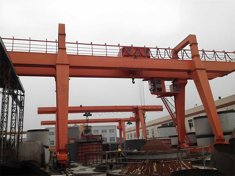
The 50-ton double girder gantry crane is a high-capacity lifting device. Its metal structure design requires comprehensive consideration of factors such as load characteristics, working environment, and usage requirements. According to the design specification, this crane must possess the function of lifting loads and moving them horizontally, enabling the placement of loads at different locations within a horizontal plane, which significantly differs from simple lifting machinery. The load-bearing beam of a gantry crane is supported by travel assemblies that run on ground rails, unlike the overhead traction units of bridge cranes, making it particularly suitable for open-air working environments.
Main Design Parameters include:
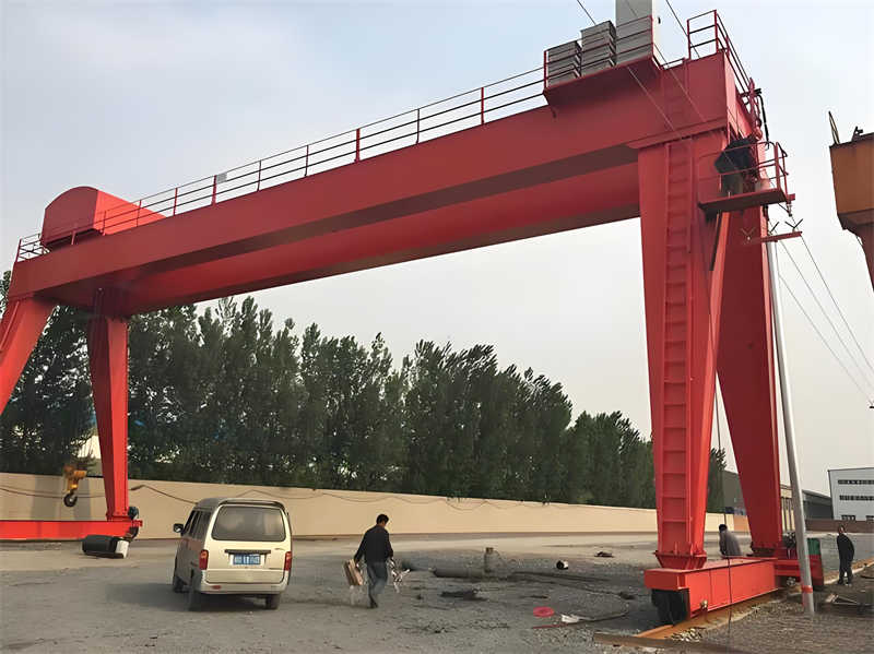
The crane’s metal structure primarily consists of two main girders and two end carriages forming a box-section frame structure. The main girders utilize a sealed box-section solid plate girder design, welded from top and bottom cover plates and two vertical web plates. The trolley travel rails are typically laid in the middle of the top cover plate of the main girders, or can be set above the inner vertical web plate. The entire structural design must comply with the requirements of the GB/T14406-93 “General Purpose Gantry Cranes” standard.
Key factors considered during the design process include:
As the core load-bearing component of the 50-ton double girder gantry crane, the main girder design directly relates to the machine’s overall safety and reliability. Based on research, this design adopts a Box Girder Structure, the mainstream form for gantry crane main girders, primarily composed of top and bottom cover plates and two vertical web plates forming a closed box-section solid plate girder. This structural form offers advantages of high stiffness, high strength, and good stability, making it particularly suitable for high-capacity equipment like the 50-ton crane.
Main Girder Cross-Sectional Dimensions are preliminarily determined as follows:
The main girder interior requires Transverse Stiffeners with spacing not exceeding the girder height, typically 1500-1800mm. Stiffener thickness matches the web plate, with a height of 1/3-1/2 of the web clear height. Local Reinforcing Stiffeners must be installed at support points and under trolley wheel loading positions to distribute concentrated loads and prevent local web buckling.
The main girder design uses an Equal Height Girder form for ease of manufacturing and installation. Considering the 50-ton capacity, the main girder requires a Pre-camber (Camber), typically about 1/1000 of the span (approx. 28mm), to counteract deflection during operation. The camber curve adopts a parabolic shape to ensure smooth trolley travel.
Main Girder to End Carriage Connection uses a flanged bolted connection, facilitating transportation and on-site assembly. The connection area is reinforced, using high-strength bolts (Grade 10.9), typically M24-M30 diameter. This connection method ensures structural integrity while allowing for on-site adjustment.
Trolley Rails, typically QU80 type dedicated crane rails, are installed on the main girders, fixed via clamps to the top cover plate. Rail installation must guarantee the following technical requirements:
Main girder manufacturing key points include:
Table: Main Girder Material List and Specifications
| Component Name | Material Grade | Specification/Dimensions | Technical Requirements |
|---|---|---|---|
| Top Cover Plate | Q345B | δ14-16 × 800-1000 | Flatness ≤2mm/m |
| Bottom Cover Plate | Q345B | δ16-20 × 800-1000 | Flatness ≤2mm/m |
| Web Plate | Q345B | δ10-12 × 1800-2200 | Verticality ≤3mm |
| Long. Stiffener | Q345B | δ10 × 150-200 | Straightness ≤2mm/m |
| Trans. Stiffener | Q345B | δ10-12 | Matched to Web Plate |
Main girder structural calculations comprise three main parts: strength calculation, stiffness calculation, and stability calculation. Strength calculation considers bending normal stress and shear stress under the Most Unfavorable Load Combination; stiffness calculation checks the Static Deflection and Dynamic Stiffness under rated load; stability calculation includes overall stability and local stability checks. Calculation results must meet the relevant requirements of GB/T3811-2008 “Crane Design Code”.
The end carriages and legs form the support system for the 50-ton double girder gantry crane metal structure. They collectively undertake the critical function of transferring loads from the main girders to the travel mechanisms and foundation rails. The end carriage, as the key component connecting the two main girders, must not only maintain their geometric positional relationship but also withstand bending and torsional loads from the main girders. The legs are the column structures connecting the end carriages to the lower travel mechanisms; their design must consider the combined action of vertical and horizontal loads.
End Carriage Structure Design adopts a box-section form, consistent with the main girder structural style. Key dimensional parameters for the end carriage include:
Transverse stiffeners are set inside the end carriage, spacing not exceeding its height. Local reinforcement is required at wheel support locations, typically using dense stiffeners or solid web construction. The connection between the end carriage and main girder uses a flanged bolted connection; the connecting surface is machined to ensure flatness, using high-strength bolts (Grade 10.9, M24-M30). This connection method facilitates on-site adjustment and reliably transfers bending moment and shear force.
Buffer Supports and Limit Switch Bumpers are installed at both ends of the end carriage. Buffers are typically hydraulic or polyurethane type, with capacity calculated based on crane mass and travel speed. The crane travel mechanism is installed under the end carriage, including drive wheel sets and idler wheel sets, often using balanced bogie structures to adapt to rail unevenness.
Leg Structure Design is a key feature distinguishing gantry cranes from overhead cranes. Based on research, this design adopts a combination of box-section Rigid Leg and Flexible Leg, typical for high-capacity gantry cranes. The rigid leg is usually rigidly connected to the main girder, transmitting both moment and shear; the flexible leg connects to the main girder via a spherical or cylindrical hinge, primarily transmitting vertical force and allowing relative rotation to accommodate structural deformation.
Key design parameters for the legs include:
The connection between the leg and end carriage uses an Integral Welded Structure, with welds requiring non-destructive testing to ensure quality. A Spherical Hinge Bearing is set at the leg bottom, allowing automatic adjustment to rail unevenness and reducing additional bending moments in the leg. The connection at the leg top to the main girder depends on the leg type: rigid legs use high-strength bolted flange connections or welded connections; flexible legs use hinged connections.
Leg structure calculations must consider the following Load Cases:
Stiffness Control for the legs is particularly important, ensuring the Relative Displacement between the two legs under load does not exceed the allowable value (typically controlled within 1/2000 of the span) to prevent excessive additional stress in the main girders. For tall leg structures, sway under wind load must also be considered; wind stays or increased leg sections can be added if necessary.
Leg manufacturing key points include:
Table: Leg Structure Parameter Comparison
| Parameter | Rigid Leg | Flexible Leg | Technical Key Points |
|---|---|---|---|
| Section Size | 1000×800 | 800×600 | Determined by reaction force |
| Plate Thickness | 16-20mm | 12-16mm | Thicker at bottom |
| Connection Type | Rigid Connection | Hinged Connection | Accommodates deformation |
| Bracing Config. | Bidirectional Bracing | Unidirectional Bracing | Enhances stability |
| Mfg. Precision | Higher | Standard | Control flange geometric tolerance |
Corrosion Protection Design for the leg structure requires special attention, as legs are close to the ground and susceptible to water splash and corrosive media. The following protective measures are recommended:
For special environments (e.g., seaside or chemical plants), Special Anti-corrosion Coatings or additional cathodic protection measures should be selected based on the corrosive media type. Drainage holes should be provided at the leg bottom to prevent internal water accumulation and corrosion.
The safety and reliability of the 50-ton double girder gantry crane metal structure must be ensured through systematic calculation and verification. Based on research, metal structure calculations primarily include checks in three areas: strength, stiffness, and stability. These calculations must follow GB/T3811-2008 “Crane Design Code” and related standards, using the allowable stress method or limit state method for verification.
Crane metal structure calculation first determines the Types of Loads and their combination methods. Loads acting on the crane metal structure mainly include:
The following Load Combinations must be considered in calculations:
The hoist load must consider the Dynamic Load Factor φ₂. For a 50-ton crane with duty class A5, φ₂ is taken as 1.1-1.2. Horizontal inertial forces from travel mechanism starting/braking are taken as 0.1-0.15 times the vertical wheel load (lower value for more drive wheels). Wind load is calculated per GB/T3811; working state uses calculated wind pressure qⅡ=0.8 kPa, out-of-service state uses value based on local 50-year recurrence basic wind pressure, but not less than 1.2 kPa.
As the primary load-bearing component, the main girder calculation is most critical. Main girder Strength Calculation includes:
Main girder Stiffness Calculation primarily checks the Static Deflection at mid-span under rated load. For the 28.5m span 50-ton crane, allowable deflection is generally L/700 ≈ 40.7mm. Calculation can ignore the hoist dynamic factor, using static load only. For frequently used cranes, Dynamic Stiffness must also be calculated, controlling the main girder’s first natural frequency to be no less than 2Hz to prevent resonance.
Main girder Stability Calculation includes:
Main Girder Calculation Example (Span L=28.5m):
Leg calculations must consider the Most Unfavorable Load Combination, typically the out-of-service maximum wind load condition. Leg calculation content includes:
For rigid legs, the Joint Strength at the connection with the main girder must be verified, including the combined tension-shear action of flange connection bolts and weld strength. Flexible legs primarily require verification of axial compression stability and the rotational capacity of the hinge joint.
Leg stability calculation uses Euler’s formula or checks per GB50017 “Standard for Design of Steel Structures”. The slenderness ratio λ of legs is typically controlled between 80-120; if too large, increase section or add lateral bracing.
End carriage calculation primarily considers the following conditions:
The connection area between the end carriage and leg requires Local Reinforcement, verifying the strength of connection bolts or welds. Transverse stiffeners are needed under the wheel support locations on the end carriage to prevent web buckling.
For cranes with duty class A5 and above, Fatigue Strength Verification is also required. According to GB/T3811, primary checks include:
Fatigue calculation uses the stress range method, determining the allowable stress range based on detail category and expected number of stress cycles. For the 50-ton crane, the fatigue life of main structural members is typically required to be no less than 2×10⁶ cycles.
A complete metal structure calculation report should include:
Calculation results must satisfy the following basic requirements:
Through systematic calculation and verification, it can be ensured that the metal structure of the 50-ton double girder gantry crane meets the requirements for safety, serviceability, and durability under various working conditions, providing an accurate basis for subsequent detailed and optimized design. Through rigorous design and manufacturing processes, the core components of the 50-ton double girder gantry crane will be precisely fabricated, ensuring dimensional accuracy and sufficient strength. Furthermore, all critical components undergo strict material selection and inspection to ensure compliance with national standards and possess excellent fatigue resistance and corrosion resistance.
Simulation analysis will model operational conditions under real working scenarios, predicting and avoiding potential safety hazards. During actual production, strict quality control will be applied to every detail, guaranteeing the manufacturing precision and assembly quality of the 50-ton double girder gantry crane.
The meticulously crafted 50-ton double girder gantry crane, following the above steps, will demonstrate outstanding performance in safety, applicability, and durability, while meeting the demands of efficient and stable operation under various complex working conditions. It will become an indispensable partner in industrial production, assisting enterprises in enhancing capacity, reducing costs, and strengthening market competitiveness.
Contact our crane specialists
Send us a message and we will get back to you as soon as possible.