Home → Gantry crane → Technical solution for single main beam hook gantry crane
Technical solution for single main beam hook gantry crane
Technical Solution for Single Girder Hook Gantry Crane
I. Project Overview
This technical solution outlines the entire process for the design, manufacture, installation, and acceptance of a single girder hook gantry crane, suitable for warehouse material handling scenarios. The scheme incorporates parameters such as workshop height (8.5m), rail surface height (350mm), and reserved space for top lighting (1000mm) to ensure the equipment meets the specific requirements of the site conditions.
II. Scope of Supply
Crane Host Machine: Includes design, manufacturing, installation, and acceptance services.
Technical Documentation: Provision of complete drawings, operation and maintenance manuals, host machine certificate of conformity, and acceptance reports for major components.
III. Main Technical Parameters
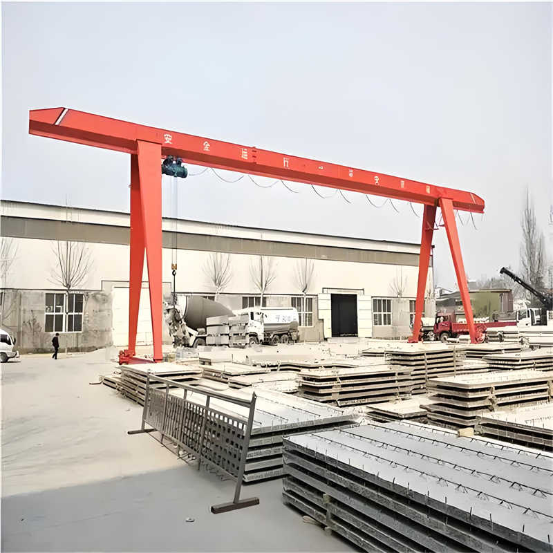
Model 1: MH5T-13.5M (Fully Enclosed Box Structure, No Cantilever)
Total Height: 7.15m (Effective Lifting Height: 5.85m)
Main Girder: Box girder structure, welded from top/bottom cover plates, web plates, and diaphragm plates, designed with camber according to specifications. Trolley rails use I-beams, with buffer stops at both ends.
Legs: Right-angled trapezoidal section box columns, with upper and lower flanges of unequal width, bolted to the main girder to form a stable “A”-shaped structure.
End Beams: Box beams connecting the legs and wheel assemblies, connected to the legs at the top and fitted with wheel assemblies or balancing bogies at the bottom.
2. Electric Hoist Assembly
Utilizes a low headroom electric hoist, integrating brake motor, reducer, drum assembly, wire rope, electric trolley, and hook assembly.
Power supply via suspended cable; electrical control system integrated within the control box.
3. Travel Mechanism
Gantry Drive: LD-type drive mechanism, installed separately on the two end beams, includes wheel assemblies, brake motors, and reducers.
Trolley Travel: Integrated with the electric hoist design, speed matched to the main hoisting mechanism.
4. Safety Protection System
Overload Limiter: Error ≤ 5%. Red indicator light activates at 90% of rated load; alarm triggers and hoisting power is cut off at 105%.
Limit Switches: Limit switches are provided for the extreme positions of all mechanisms. Additional height limit switch for the hoisting mechanism; automatically cuts power and alarms when limits are exceeded.
Lubrication System: Independent lubrication devices for wheels, gearboxes, etc.; lubrication maintenance performed according to standards.
5. Materials and Components
Main Material: Q235B steel plate
Wheels: Cast steel double-flange wheels (Complies with GB4628 standard)
Bearings: LYC brand bearings
V. Electrical System Design
1. Power Supply Configuration
Three-phase AC 380V/50Hz power supply. Main power is introduced via conductor bars to the control box, equipped with a main circuit breaker for short-circuit and overload protection.
Control circuit includes start, stop, and directional control buttons, supporting independent operation of each mechanism.
2. Control System
Independent Control Circuits: Separate circuits for each mechanism, equipped with travel limit protection.
Bi-directional Limiting: Bi-directional limit switches for the electric hoist and gantry travel mechanisms; upper hoisting limit switch for the hoisting mechanism.
Check component list, inspect parameters like main girder camber and sweep, repair transport damage, and touch up paint.
Develop construction plan and safety measures, clearly defining personnel responsibilities.
2. Main Structure Erection
End Beam and Leg Assembly: Position end beams using a crane, adjust span and diagonal errors, secure with guy ropes to ensure vertical alignment.
Main Girder Hoisting: Hoist main girder using a mobile crane, align and weld or bolt to legs after positioning.
Auxiliary Structure Installation: Weld operator’s cab, platform, ladders, etc. Hoist and install the trolley, and install the weather canopy.
3. Electrical Installation
Electrical equipment installed per GBT14406-93 standard. Resistor vertical tilt ≤ 1/200. Wires laid in cable trays, with separate conduit protection for different mechanisms.
Grounding Protection: Reliable grounding for all electrical equipment enclosures, metal conduits, etc.
Insulation Test: Insulation resistance of motors and circuits ≥ 1MΩ.
4. Lubrication and Test Run
Lubrication: Fill reducers with No. 90 industrial gear oil; fill brake actuator with No. 10 aviation hydraulic oil; apply lithium-based grease to bearing housings.
No-Load Test: Start equipment under specialized supervision, check operational status. Proceed to load test after eliminating any abnormalities.
VII. Acceptance Standards
After equipment installation and commissioning are complete, acceptance will be carried out according to relevant national standards and contract requirements to ensure performance parameters and safety indicators are met.
Contact our crane specialists
Send us a message and we will get back to you as soon as possible.