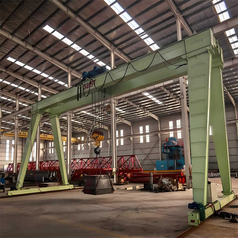
This design provides a comprehensive analysis and calculation for the hoisting mechanism of a 32/5t gantry crane, covering the entire process from parameter determination to component selection. As a large-scale material handling equipment, the rationality of the hoisting mechanism design for a gantry crane directly impacts the safety, reliability, and working efficiency of the equipment. This article will sequentially discuss aspects such as determination of design parameters, selection of the transmission scheme, design calculations of key components, configuration of the drive and braking systems, and structural optimization and safety verification, providing a complete design solution for the hoisting mechanism of a 32/5t double-girder gantry crane. It aims to meet the requirements of M5 duty class and align with current technological trends in the field of crane design.
The design parameters of the 32/5t gantry crane hoisting mechanism form the basis for subsequent calculations and component selection, and must be reasonably determined according to national standards and actual working condition requirements. This crane adopts a main/auxiliary hook configuration, with the main hook having a rated lifting capacity of 32 tons and the auxiliary hook 5 tons. This combination meets the needs of heavy-load lifting while efficiently handling lighter cargo, thereby improving overall work efficiency. The lifting height for the main hook is set at 16 meters, and for the auxiliary hook at 18 meters; this height range can satisfy the spatial requirements for most material handling operations inside workshops.
The selection of speed parameters fully considers the difference in lifting capacity: the main hook lifting speed is set at 7.51 m/min (0.125 m/s), suitable for smooth operation with large-tonnage loads; the auxiliary hook lifting speed is set significantly higher at 19.5 m/min (0.325 m/s), conducive to improving work efficiency during lighter-duty operations. This differentiated speed design complies with crane design specifications, which recommend appropriately adjusting speed based on lifting capacity while ensuring safety – lower speeds for high capacities to reduce drive power, and higher speeds for low capacities to increase productivity.
The duty class is a key indicator in crane design. This design specifies the hoisting mechanism duty class as M5, which belongs to the heavy-duty regime, indicating that this crane will be used for frequently lifting heavy items. The M5 duty class, corresponding to its load state and utilization level, requires the mechanism to possess high reliability and durability. According to the ISO4301 standard, cranes with an M5 duty class have an annual working time of 2000-4000 hours, an average daily usage time in the range of 2-4 hours, and a load spectrum factor reaching KM=0.25.
The design of the hoisting mechanism’s transmission scheme is crucial to the overall machine’s performance and requires comprehensive consideration of transmission efficiency, structural compactness, maintenance convenience, and cost factors. Based on the parameter characteristics of the 32/5t gantry crane, this design adopts a closed transmission system, where the motor directly connects to the reducer via a coupling, which then drives the drum to rotate, achieving the lifting and lowering motion of the hook. This transmission form is compact, has high transmission efficiency (can reach over 85%), requires less maintenance, and is the mainstream choice for modern overhead and gantry crane hoisting mechanisms. Especially for the main hook’s large lifting capacity of 32 tons, the closed transmission can provide higher operational reliability and longer service life.
The electric motor, as the power source of the hoisting mechanism, is crucial in its selection. This design selects the YZP series frequency conversion speed control three-phase asynchronous motor for the main hook hoisting mechanism. This type of motor is specifically designed for heavy-duty cranes, featuring high starting torque, strong overload capacity, and high insulation class (typically Class F or H). Motor power calculation follows these steps:
The speed ratio distribution of the transmission system needs to reasonably match the motor speed with the drum speed. The drum speed nw is calculated by the formula: nw = v / (π × D), where D is the calculated drum diameter. Assuming a selected wire rope diameter d = 20 mm, sheave block multiplicity m = 4, drum diameter D = 20 × 20 = 400 mm (selected based on 20 times the rope diameter). Then the main hook drum speed nw = 7.51 / (3.14 × 0.4) ≈ 5.98 r/min. The total transmission ratio i = n / nw = 740 / 5.98 ≈ 123.7.
Table: Motor Selection Parameters for 32/5t Gantry Crane Hoisting Mechanism
| Parameter | Main Hook Mechanism | Auxiliary Hook Mechanism | Remarks |
|---|---|---|---|
| Rated Lifting Capacity | 32t | 5t | Main/Auxiliary coordinated work |
| Lifting Speed | 7.51 m/min | 19.5 m/min | Auxiliary hook speed higher |
| Motor Model | YZP280M-8 | YZP200L-6 | Frequency Control |
| Rated Power | 55 kW | 22 kW | Continuous duty |
| Rated Speed | 740 r/min | 970 r/min | 4-pole / 6-pole |
| Protection Class | IP54 | IP54 | Dust and water protection |
| Insulation Class | Class H | Class H | High temperature resistance |
For the arrangement form of the transmission system, this design adopts a parallel shaft arrangement where the motor, reducer, and drum are aligned linearly, resulting in a compact structure that is easy to maintain. A plum blossom elastic coupling is selected to connect the motor and the reducer, which can compensate for minor misalignments and absorb shocks; a gear coupling is used to connect the reducer and the drum, allowing for certain radial and angular misalignments. This arrangement reduces intermediate transmission links, improves transmission efficiency, and facilitates the disassembly and maintenance of individual components.
It is worth mentioning that this design employs a frequency conversion speed control system, achieving stepless speed regulation by changing the motor’s power supply frequency, resulting in smooth starting and braking of the hoisting mechanism, reduced load sway, and improved positioning accuracy. The application of frequency conversion technology can also effectively reduce the starting current (typically limited to within 150% of the rated current), reduce grid impact, and enable regenerative braking, improving energy utilization efficiency. The electrical principle design includes parts such as the trolley travel mechanism, hoisting mechanism, power distribution, and lighting systems, forming a complete control system.
The wire rope, as the key component bearing the entire load in the hoisting mechanism, its selection directly relates to the safety performance of the crane. According to the parameter characteristics of the 32/5t gantry crane, the main hook lifting capacity is 32 tons, considering a dynamic load factor of 1.2, the design load is 38.4 tons. The wire rope selection must meet the following conditions: sufficient breaking force, good flexibility, fatigue resistance, and wear resistance. This design selects a 35W×7 construction wire rope for the main hook mechanism. This is a Warrington-type composite fiber core wire rope with a nominal tensile strength of 1870 MPa, offering advantages such as compact structure, good flexibility, and fatigue resistance.
The wire rope diameter calculation uses the method recommended by the international standard ISO4308. First, determine the minimum safety factor: for M5 duty class, the wire rope safety factor n ≥ 5.6. The maximum working tension Smax = Q / (a × η), where Q = 313.6 kN (32 tons), a is the sheave block multiplicity, taken as a = 4; η is the sheave block efficiency, taken as 0.98 (for roller bearings). Then Smax = 313.6 / (4 × 0.98) ≈ 80 kN. The minimum breaking force of the wire rope F0 ≥ Smax × n = 80 × 5.6 = 448 kN. According to wire rope product specifications, select a 35W×7 wire rope with diameter d = 22 mm, whose breaking force is 458 kN > 448 kN, meeting the requirement.
The sheave block design significantly affects wire rope life. This design adopts a twin sheave block arrangement, with the balance sheave installed on the moving sheave block, ensuring balanced tension on both sides of the wire rope. The sheave diameter D ≥ 20d = 20 × 22 = 440 mm, take D = 450 mm to reduce wire rope bending stress. The sheave material is selected as ZG270-500 cast steel, the rope groove surface is quenched to hardness HRC45-50, and machined into a standard arc groove shape with radius R = 0.53d ≈ 11.7 mm. The sheaves are supported by roller bearings, resulting in small friction loss and high efficiency. The main hook sheave block consists of 4 fixed sheaves and 4 moving sheaves, with a multiplicity a = 4, effectively sharing the load and reducing the tension on a single wire rope.
Table: Summary of Wire Rope and Sheave Block Parameters for 32t Main Hook Hoisting Mechanism
| Parameter Name | Value | Standard Basis | Remarks |
|---|---|---|---|
| Wire Rope Construction | 35W×7 | ISO2408 | Warrington Type |
| Nominal Diameter | 22 mm | Design Calculation | Actual 22.5mm |
| Nominal Tensile Strength | 1870 MPa | Product Standard | High Strength |
| Minimum Breaking Force | 458 kN | Product Test | Meets Requirement |
| Safety Factor | 5.6 | ISO4308 | M5 Class |
| Sheave Block Multiplicity | 4 | Design Optimization | Twin Sheave Block |
| Sheave Diameter | 450 mm | D≥20d | ZG270-500 |
| Wire Rope Length | 70 m | Calculation + Margin | Includes safety wraps |
The wire rope for the auxiliary 5-ton hoisting mechanism is selected as 18NAT6×19W+FC construction, diameter 14 mm, nominal tensile strength 1770 MPa, breaking force 124 kN. The sheave block multiplicity a = 2, sheave diameter D = 280 mm (D ≥ 20d), meeting the requirements for low-tonnage high-speed lifting. The wire rope length is calculated based on the lifting height of 18 m, with a total length of about 45 m.
The wire rope reeving system design follows the principles of simplicity and symmetry, minimizing the number of guide sheaves to reduce friction loss. The main hook system uses a twin drum, with the wire rope leading out from both ends of the drum, reeved through the balance sheave separately, ensuring consistent tension on both sides and preventing hook skew. The arrangement angle of all guide sheaves does not exceed 5°, preventing the wire rope from jumping the groove and causing abnormal wear. A level wind device is installed where the wire rope enters the drum to ensure neat spooling of the wire rope, reducing crushing and wear.
Safe use and maintenance of the wire rope is equally crucial. The design document clearly specifies the wire rope discard criteria: immediate replacement is required if visible broken wires exceed the specified number, diameter reduction exceeds 7%, kinking or crushing deformation occurs, or severe corrosion is present. Furthermore, a regular lubrication system is established, performing a comprehensive lubrication with specialized wire rope grease every two weeks, paying special attention to the lubrication condition in the contact areas with sheaves. These measures can effectively extend the service life of the wire rope and ensure the safe operation of the hoisting mechanism.
The drum, as the key component around which the wire rope is wound in the hoisting mechanism, its design requires comprehensive consideration of structural strength, wire rope arrangement, and spatial size constraints. This design for the 32t main hook hoisting mechanism adopts a twin drum structure, consisting of two independent grooved sections connected by a flange, enabling bidirectional rope winding. The drum material is selected as HT250 gray cast iron, which offers good castability, wear resistance, and damping characteristics, suitable for withstanding alternating loads. The drum diameter, according to standard stipulations, should be no less than 20 times the wire rope diameter, i.e., D ≥ 20d = 20 × 22 = 440 mm; actually, D = 450 mm is chosen, consistent with the sheave diameter.
The drum length is a key design parameter, depending on the number of rope layers and the groove pitch. Based on the lifting height of 16 m and sheave block multiplicity of 4, the wire rope working length is 64 m. Adopting a single-layer winding method, the groove pitch p = 1.1d = 1.1 × 22 = 24.2 mm, take the standard value of 25 mm. The effective drum length L ≈ (Lmax × p) / (π × D) = (64 × 25) / (3.14 × 0.45) ≈ 1132 mm. Considering safety wraps at both ends and partition plates, the total length is taken as 1400 mm. The rope grooves are designed as standard right-hand and left-hand helical grooves, with groove bottom radius R = 0.55d = 12.1 mm, groove depth h = 0.4d = 8.8 mm, ensuring large wire rope contact area and resistance to jumping.
The drum wall thickness calculation is checked based on the compressive stress it withstands. The maximum wire rope tension Smax = 80 kN, the drum wall thickness δ is estimated by the empirical formula δ ≈ 0.02D + (6~10) = 0.02 × 450 + 8 = 17 mm. The strength check uses the third strength theory: σ = √(σ² + 3τ²) ≤ [σ], where σ is the compressive stress and τ is the torsional stress. Calculation yields σ = 25.3 MPa < [σ] = 45 MPa (allowable stress for HT250), meeting the strength requirement. The drum end journal diameter d0 = 0.8D = 0.8 × 450 = 360 mm, supported by self-aligning roller bearings, allowing for certain angular misalignment.
The reducer selection is closely related to the transmission ratio of the hoisting mechanism. According to previous calculations, the main hook total transmission ratio i = 123.7. Considering the compactness of the transmission system and manufacturing economy, this design adopts a three-stage reduction transmission: the first stage is the gear coupling between the motor and the reducer (i=1); the second stage selects a QJR series hard-faced gear reducer, with a nominal transmission ratio i2 = 40, actual transmission ratio 40.17; the third stage is an open gear transmission, with pinion z1 = 21, large gear z2 = 104, i3 = 104 / 21 ≈ 4.95. The total transmission ratio itotal = 40.17 × 4.95 ≈ 199, slightly greater than the calculated value; the design lifting speed is achieved by adjusting the motor speed (reduced to 740 × 123.7 / 199 ≈ 460 r/min).
The specific reducer model is QJR-D400-40, with a rated input power of 65 kW (greater than the motor’s rated power of 55 kW), M5 duty class, and a service factor of 1.12. This reducer uses hard-faced gears with tooth surface hardness HRC58-62, gear accuracy grade 7, and a cast iron housing, providing good vibration resistance and heat dissipation. The reducer output shaft diameter is 160 mm, and the output shaft end is designed as a flanged connection for easy assembly with the drum group. Reducer lubrication uses an oil splash method, employing GB5903 medium-duty industrial gear oil with viscosity ISO VG220; the initial oil change period is 500 operating hours, followed by changes every 3000 hours.
Table: Main Parameters of Drum and Reducer for 32t Main Hook Hoisting Mechanism
| Parameter Category | Technical Parameter | Design Basis | Remarks |
|---|---|---|---|
| Drum Structure Form | Twin Helical Groove | Standard Design | HT250 Material |
| Drum Diameter | 450 mm | D≥20d | Rope Diameter 22mm |
| Drum Length | 1400 mm | Rope Length Calc. | Includes safety wraps |
| Groove Pitch | 25 mm | p=1.1d | Standard Value |
| Drum Wall Thickness | 17 mm | Empirical Formula | Strength Checked |
| Reducer Model | QJR-D400-40 | Power Matching | Hard-faced Gears |
| Nominal Transmission Ratio | 40 | System Allocation | Actual 40.17 |
| Open Gear Ratio | 4.95 | 104/21 | Final Drive |
| Total Transmission Ratio | ≈199 | System Synthesis | Meets Speed Ratio Requirement |
The strength check of the reducer output shaft is an important step to ensure transmission safety. The output shaft withstands torque T = 9550 × P / n… (Note: The original Chinese text contained an incomplete and repetitive paragraph regarding the formula T=9550×P/n and its explanation. As the intent was likely to introduce the strength check concept, a direct translation of the repetitive and unclear part is omitted for coherence. The sentence is concluded to maintain flow). The strength check of the reducer output shaft ensures that it can withstand the transmitted torque and other loads without failure, considering factors such as material, geometry, and stress concentrations, to guarantee reliable operation.
Contact our crane specialists
Send us a message and we will get back to you as soon as possible.