Home → Gantry crane → Installation Work Instruction for 10-ton Gantry Crane
Installation Work Instruction for 10-ton Gantry Crane
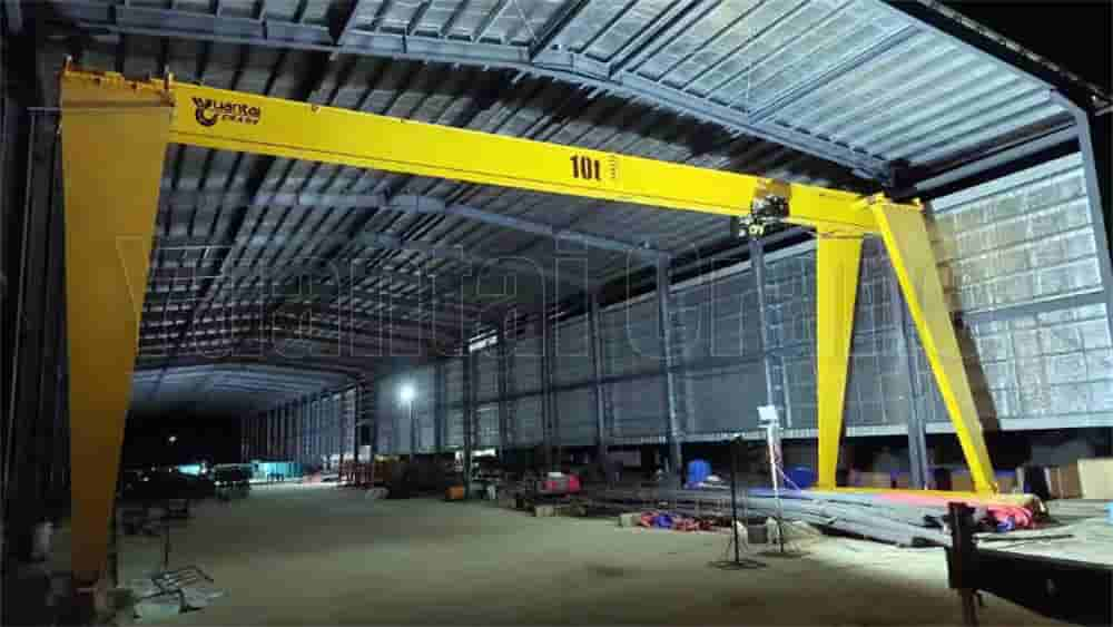
I. Project Overview
This instruction applies to the installation of a 10-ton gantry crane. This equipment is intended for use at a certain steel rolling project production site in Tangzhong and is classified as large-scale lifting equipment (total weight approx. 40 tons). As the equipment is a used machine transported after disassembly, special attention must be paid to checking for structural deformation and component damage. The installation process is complex and labor-intensive. This instruction is formulated specifically to ensure construction safety and efficiency.
II. Basis for Compilation
Code for Construction and Acceptance of Crane Equipment Installation Engineering (GB50238-98)
General Code for Construction and Acceptance of Mechanical Equipment Installation Engineering (GB50231-98)
Safety Operation Procedures and Lifting Machinery Technical Manual
Code for Construction and Acceptance of Steel Structure Engineering (GB50205-2001)
Technical Specification for Operation of High-Strength Bolt Assemblies
III. Pre-Installation Preparation
(A) Site Requirements
Track foundation bearing capacity ≥ 20 N/cm². Compact with a bulldozer before laying and test the compressive resistance coefficient.
Gravel layer thickness ≥ 500mm, compacted layer by layer before laying sleepers (specification: 1250×200×200mm).
(B) Equipment and Tools
Main Components: Rails (80 pieces, single length 12.5m, weight 0.537t), Beams (28 pieces, single weight 13.4t), Crane Columns (8.5m height, single weight 3.8t), Electric Hoist (3.3t), and ancillary facilities.