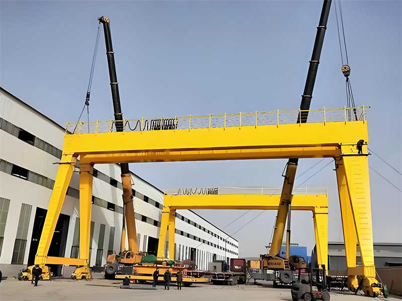
As a key lifting equipment in the heavy industry sector, the 150T Gantry Crane is renowned for its exceptional load-bearing capacity and stable operational performance. This equipment adopts a modular design concept and is equipped with an advanced electrical control system, ensuring efficient operation under various complex working conditions. Its application scope covers multiple industrial fields, from port container handling to large steel structure installation, and from heavy machinery manufacturing to energy equipment lifting. The entire machine structure is optimized through finite element analysis, with key components manufactured from high-strength alloy steel, coupled with multiple safety protection devices, providing reliable assurance for heavy material handling.
The 150T Gantry Crane is a core piece of heavy industrial equipment, specifically designed to meet high-intensity operational demands such as large component lifting and heavy equipment transportation. It adopts a double girder box-type structural design, with a rated lifting capacity of up to 150 tons, and a customizable span range of 20-35 meters based on actual requirements. The main steel structure utilizes Q345B low-alloy high-strength steel to ensure structural strength and stability. Through advanced finite element analysis methods, the structure is optimally designed, resulting in more reasonable stress distribution. The main girder deflection is strictly controlled within 1/800 of the span, effectively avoiding lifting errors caused by deformation.
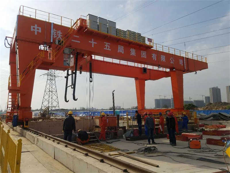
The portal frame structure of this gantry crane, combined with an eight-wheel bogie travel mechanism, allows for flexible movement and maintained stable performance in open-air working environments. Its duty grade meets the A5 standard, meaning it can maintain efficient and reliable operation even under harsh conditions.
The 150T Gantry Crane is specifically designed for large component lifting and heavy equipment transportation, widely used in scenarios such as block assembly in shipyards, boiler installation in thermal power plants, and lifting of bridge precast components. The ambient temperature adaptation range is -20°C to +50°C, with maximum wind resistance capability up to Grade 6 (wind speed 13.8 m/s). Track installation must meet the requirements of the GB/T10183-2005 standard. Use in flammable, explosive, or strongly corrosive media environments is prohibited to ensure equipment safety and reliability.
This gantry crane employs a double main girder box-type structural design, which not only enhances overall stability but also effectively reduces the load pressure per unit area. The design of four rigid supporting legs further strengthens the rigidity and stability of the overall structure, allowing the entire crane to maintain precise geometric shape and dimensions even under heavy loads. The hoisting mechanism is one of the core components of this gantry crane. It uses a 42CrMo alloy steel drum paired with multi-layer wound wire rope, ensuring no slipping or breakage occurs during high-intensity operations. The equipped imported Dutch WST series overload limiter effectively prevents safety accidents caused by overloading. The gantry travel mechanism adopts a triple-reduction gear motor drive method. This design not only improves operating efficiency but also allows the travel speed to be flexibly adjusted within the range of 5-30 m/min according to actual needs. The electrical system is equally uncompromising, configured with a control cabinet with IP55 protection rating. This level of protection effectively prevents the ingress of dust and water, ensuring the stability and safety of the electrical system. Key circuits are equipped with double insulation protection measures, further enhancing the equipment’s safety performance.
The rated load of this crane is 150 tons, meaning it can safely lift and transport cargo weighing 150 tons. Under the rated load, its lifting height can reach 18 meters above the rail and 6 meters below the rail, providing great flexibility and convenience for operations. Furthermore, its hoisting speed can be steplessly varied between 0.5-5 meters/minute, further improving operational efficiency. The standard configuration for the main girder span is 30 meters, with a cross-sectional dimension of 2.8×3.2 meters, a design that ensures the crane’s stability and safety. The end girder wheelbase is 8 meters, making the entire machine more stable during operation. The total weight of the machine is approximately 280 tons (excluding counterweight), a weight distribution that helps maintain the machine’s balance and stability. The operating power supply is AC380V±10%, 50Hz three-phase five-wire system, ensuring the machine can operate normally under various voltage fluctuations.
The hoisting mechanism of this crane is configured with two 75kW wound rotor motors. The brake torque is not less than 1.8 times the rated torque, ensuring stability and safety during cargo lifting. The trolley travel speed can be adjusted via frequency control within the range of 2-20 meters/minute, while the positioning accuracy is as high as ±10mm, greatly improving operational efficiency. The gantry travel system uses 16 sets of 45kW drive units, equipped with anti-wind anti-slip rail clamps, enabling stable operation in various complex environments. The overall noise level is ≤85dB(A), and the insulation resistance is ≥1MΩ, fully reflecting its efficient and stable characteristics.
The electrical system of this crane possesses excellent performance and protection functions. The short-circuit breaking capacity of the main circuit reaches 50kA, ensuring system safety and reliability. The control voltage uses a DC24V safety voltage, further enhancing system security. It is configured with a Siemens S7-1200 PLC control system, featuring overcurrent, undervoltage, and phase sequence protection functions, effectively protecting the system from various electrical faults. Furthermore, the frequency converter uses the ABB ACS880 series, with adjustable carrier frequency of 4kHz, not only improving the system’s response speed and precision but also reducing energy consumption and noise. For the lighting system, this crane is equipped with 8 pieces of 100W LED explosion-proof lights, with an illuminance of ≥150 lux, making the work site brighter and safer.
Before installation, it must be ensured that the foundation’s bearing capacity meets the design requirements, reaching at least 250 kPa, to guarantee the equipment’s stability and safety during use. For track installation, the straightness deviation must not exceed 2mm/10m, which is an important condition for ensuring smooth and precise equipment operation. On site, specialized tools such as a 200-ton mobile crane and a laser theodolite need to be prepared for lifting and measurement work during the installation process. Additionally, it is necessary to carefully check the parts list and assembly drawings to ensure all necessary parts are available and match the drawings. Perform non-destructive testing on track joints, and control the track gauge tolerance within ±5mm to ensure the safety and stability of the track joints.
During the installation process, first re-measure the track to ensure its straightness meets requirements, and adjust the base plates to ensure the flatness and stability of the entire installation foundation. Next, use a 200-ton mobile crane to sequentially hoist and install components such as the legs, main girder, and trolley, ensuring the accurate installation position of each component. For high-strength bolts, tighten them in three stages according to the GB/T1228 standard, ensuring the torque deviation does not exceed ±5% to guarantee the tightness of the bolts and the safety of the connections. During the laying of electrical wiring, maintain a safe distance between the wiring and moving parts to prevent issues caused by wire wear, and control the grounding resistance below 4Ω to ensure the safety and stability of the electrical system.
Before no-load trial operation, the effectiveness of all limit switches must be checked to ensure the equipment can accurately trigger the limit switches during operation, avoiding equipment damage or safety accidents due to limit switch failure. Gradually test the acceleration curves of the hoisting and travel mechanisms to check if the equipment’s dynamic performance meets design requirements. Load testing is carried out in stages: 110% rated load static test and 125% dynamic test, to verify the equipment’s load-bearing capacity and operational stability. During the commissioning process, focus on monitoring motor temperature rise and structural component deformation, ensuring that no problems arise during operation due to excessive temperature or structural deformation. Simultaneously, pay attention to following relevant safety regulations and operating specifications to ensure the safety and reliability of the commissioning process.
Before initiating any operation, it is crucial to first conduct a detailed inspection of key components. For the wire rope, its wear condition must be checked, including but not limited to the number of broken wires, ensuring the breakage rate does not exceed 10%. At the same time, there are strict requirements for the thickness of the brake liner, which must retain at least 50% of its original thickness to ensure braking effectiveness and safety. Additionally, it is necessary to confirm that all emergency stop buttons function normally, ensuring the equipment can be stopped quickly and effectively in an emergency. The anemometer reading is also an important indicator for observing environmental safety; if the wind speed exceeds 10.8 m/s, protective measures may be required. Operators must hold a valid Q2 Special Equipment Operation Certificate and should be familiar with the layout of the 18 function keys on the control panel to perform tasks quickly and accurately during operation.
After completing all safety checks, turn on the power and start the PLC self-test program to ensure the control system is operating normally. First, start the lubrication system oil pump to provide good lubrication conditions for various moving parts. During lifting operations, strictly adhere to the principle of “lift and lower loads gently, accelerate smoothly” to avoid impact loads damaging the equipment. When multi-agency collaboration is required, a certain priority sequence should be followed: start the hoisting mechanism first, then the trolley travel mechanism, and finally the gantry travel mechanism. Under no circumstances should the load be pulled or lifted at an angle to prevent the goods from falling off or the equipment from being damaged. At the same time, the suspension time of the load should also be strictly controlled, generally not exceeding 30 minutes, to avoid unnecessary energy consumption and equipment wear.
After completing tasks, stop all mechanisms at designated positions according to the correct sequence, ensuring the hoisting wire rope remains slightly tensioned to prevent slackness that could lead to instability. Before cutting the main power supply, be sure to confirm that all mechanisms have completely stopped operating, and record detailed operational data for the shift for subsequent analysis and maintenance. Especially in winter, due to low temperatures, accumulated water in cooling water pipes may freeze. Therefore, after shutdown, this accumulated water needs to be drained promptly. Simultaneously, apply anti-rust grease to exposed gears and other key components to prevent moisture and corrosion from adversely affecting the equipment.
Daily maintenance is the foundation for ensuring normal equipment operation and typically includes, but is not limited to, the following aspects:
To ensure long-term stable operation of the equipment, in addition to daily maintenance, a periodic maintenance plan needs to be established, mainly including the following:
Table: 150T Gantry Crane Periodic Maintenance Schedule
| Maintenance Item | Inspection/Operation Content | Cycle/Standard | Key Parameters/Requirements | Tools/Materials | Precautions |
|---|---|---|---|---|---|
| Wire Rope Check & Lube | Check wear, broken wires; Apply grease | Daily | Wear <10% diameter; Lubricate evenly | #2 Lithium Grease, Caliper | Avoid inferior grease |
| Brake Performance Test | Test response time & braking force | Weekly | Response ≤0.3s; Brake force 125% rated | Stopwatch, Pressure Sensor | Test 3 times no-load after adjustment |
| Rail Surface Maintenance | Remove metal chips, debris | Daily | Rail levelness ≤1/1000 | Scraper, Vacuum | No corrosive cleaners |
| Gearbox Oil Change | Drain old oil, refill new oil | Every 500 hours | ISO VG320 grade oil | Oil Pump, Waste Oil Can | Clean sump when changing oil |
| Main Girder Camber Check | Laser measure girder deflection | Annual | Upper camber 0.9-1.4L/1000 | Laser Rangefinder | Must be unloaded state |
| Weld NDT | Magnetic particle inspection on main load welds | Annual | No cracks, lack of fusion defects | MPI Tester | Clean weld surface before inspection |
Table: 150T Gantry Crane Common Fault Handling Table
| Fault Phenomenon | Possible Cause | Diagnostic Method | Handling Measures | Tools/Spare Parts | Safety Warning |
|---|---|---|---|---|---|
| Motor Overheat | Abnormal VFD carrier freq/Poor cooling | IR thermometer check; Check fan operation | Adjust carrier freq to 2-6kHz; Clean cooling passages | Multimeter, Air Blower | Power off before work, prevent shock |
| Brake Slipping | Insufficient spring pressure/Worn lining | Pressure test; Visual check wear | Adjust spring pressure to 125% rated; Replace linings worn >2mm | Pressure Wrench, Feeler Gauge | Perform static load test after adjustment |
| Rope Rope Jumping Groove | Pulley misalignment/Loose end fixings | Plumb line check alignment; Check fixing bolts | Correct pulley group alignment (<1° deviation); Retighten fixing bolts | Laser Aligner, Torque Wrench | Lock hoisting mechanism during work |
| Electrical Cabinet Fault | Dust accumulation/Aged components | Insulation resistance test; Visual check | Dust with 0.2MPa air; Replace failed components | Megohmmeter, ESD Brush | No live work |
| Gearbox Abnormal Noise | Gear wear/Contaminated oil | Vibration analysis; Oil quality check | Change oil; Replace assembly if gear pitting area >20% | Vibration Analyzer, Oil Tester | Do not open inspection port while running |
During equipment operation, some common faults may occur. Corresponding handling methods should be adopted for these faults:
When lifting long items, tag lines must be used to prevent the load from swinging or falling during transport. During trial lifts, maintain a load height of 0.5 meters above the ground to check the stability and safety of the lifting equipment. Repairing or maintaining equipment with a load suspended is strictly prohibited to avoid accidents caused by improper operation. In thunderstorm weather, stop operations immediately to ensure operator safety. The operating cab should be equipped with fire extinguishers and emergency communication devices for self-rescue and calling for help in emergencies. Furthermore, operators must possess appropriate qualifications and skills, comply with relevant regulations and operating procedures to ensure the safety and smooth progress of operations.
The hoisting height limiter adopts a dual independent system design: the first set is an electrical control device, and the second set is a mechanical weight-type device, ensuring safety and reliability. Hydraulic buffers and polyurethane bumpers are installed at the ends of the gantry travel to absorb impact forces during travel and prevent collision damage. All exposed rotating parts are fitted with protective covers, ensuring operator safety while enhancing the overall aesthetics of the equipment. The implementation of these protective measures will effectively guarantee safety and stability during equipment operation.
To deal with unexpected situations, the equipment is equipped with a brake holding device, ensuring the equipment remains safely in place in case of sudden power failure. Simultaneously, the battery-powered emergency lighting system can provide 90 minutes of continuous illumination after a power outage, giving operators sufficient time for emergency handling. For wind speeds ≥16 m/s, the rail clamps are automatically triggered to enhance the equipment’s wind resistance and anti-slip capability, ensuring the equipment remains stable under severe weather conditions. To further improve response capability, the company has also developed special emergency plans for possible emergencies and conducts simulation drills quarterly to ensure operators can respond quickly and effectively to various unexpected situations.
This standard configuration includes four sets of 10-ton lifting spreader beams, designed to enhance the stability and safety of lifting operations; two sets of wireless remote controllers with an effective control range of 100 meters, ensuring operational flexibility and real-time control; also includes sixteen pieces of rail clamps, used to secure and protect the rails, ensuring smooth operation of the lifting equipment. The randomly provided specialized wrench set and hydraulic torque wrench ensure precise fastening operations; the lubrication grease gun maintains good lubrication of the equipment, extending its service life. The accompanying technical documentation package is comprehensive: the general layout drawing gives users a clear overview of the equipment layout, electrical schematic diagrams facilitate later maintenance and troubleshooting, and the wear parts list clarifies the replacement cycle and requirements for various components, providing detailed guidance for maintenance work.
To meet users’ diverse practical needs, we provide a series of optional accessories to enhance the equipment’s functionality. For example, the laser anti-collision system can effectively prevent collisions during lifting operations within a 30-meter detection range, ensuring safe and efficient operation; the load dynamic monitor provides real-time monitoring of the lifted load weight with ±1% accuracy, ensuring safe and reliable operation. Furthermore, the electromagnetic beam and rotating hook provide convenience and flexibility for steel plate lifting and multi-functional lifting operations respectively; the rotating hook can achieve ±180° rotation, greatly improving lifting efficiency. For application requirements in extreme environments, we specially offer a heated control cabinet that can maintain normal operation even at temperatures as low as -40°C.
To ensure the continuous and stable performance of the equipment, perform a signal strength test on the wireless remote controller at least once a month to ensure good transmission efficiency; simultaneously, the battery life must be no less than 8 hours to avoid affecting normal use due to insufficient power. For key components like the spreader beam pins in the standard configuration, perform non-destructive testing every six months. If wear exceeds 2% of the diameter, they must be replaced immediately to ensure the safety of lifting operations. For the scraper in the track cleaning device, when its thickness is reduced to below 5mm, a full replacement is recommended to maintain track cleanliness and extend service life.
Our after-sales service team provides round-the-clock, comprehensive 48-hour on-site response service. Wherever and whenever you encounter problems, we will dispatch professional technicians to your site at the first opportunity to provide solutions. To better support customers, we also provide a remote diagnostic system. Through real-time data transmission functionality, technicians can promptly and accurately determine the problem, greatly improving repair efficiency. To ensure the long-term stable operation of the equipment, we arrange quarterly preventive maintenance inspections to conduct comprehensive checks and maintenance on the equipment, ensuring its performance remains in optimal condition. Additionally, we will establish a full lifecycle file for each piece of equipment, recording information such as purchase, use, and maintenance, to better track equipment status and provide customers with higher quality after-sales service.
The warranty period for the steel structure is 5 years, which is our confidence in quality and commitment to customers. During the warranty period, we will provide free repair services for any quality issues that arise. The mechanical transmission system enjoys a 2-year warranty period. During this period, if problems occur due to manufacturing defects, we will also provide free repair services. The warranty period for electrical components is 1 year. We understand the importance of electrical components to the equipment, so within this year, if any problems occur with electrical components, we will provide you with timely repair services. It is important to note that人为损坏 (man-made damage) and wear parts are not covered by the warranty. Furthermore, if the equipment malfunctions due to overload use, our warranty responsibility is automatically terminated. However, we will still provide paid repair services. During the warranty period, we also provide free technical consultation and software upgrade services. Whenever you encounter any problems or doubts, you can contact our customer service center or after-sales team at any time. We are committed to answering your questions and providing professional advice.
| (Note: Parts of this document may be generated by AI)
Contact our crane specialists
Send us a message and we will get back to you as soon as possible.