This design proposes a complete structural design plan for an 18-ton/5-ton 40-meter Type-A Double-Girder Gantry Crane to meet the loading and unloading operational needs of port freight yards. The equipment adopts a double main girder box-type structure, equipped with rigid and flexible legs. It features a large span, good stability, and a wide operational range, effectively improving port freight yard loading/unloading efficiency and reducing worker labor intensity. The following provides a detailed explanation from multiple aspects such as technical parameters, overall structure, main girder design, leg system, and strength calculations.
A Type-A Double-Girder Gantry Crane is a large-scale material handling equipment whose structural design directly affects load-bearing capacity and operational stability. The designed 18/5t-40m Type-A Double-Girder Gantry Crane is a medium-to-large lifting device. The main and auxiliary hook configuration meets the lifting needs of materials of different weights, and the 40-meter span design is suitable for large freight yard operations.
Main Technical Parameters:
Duty Class: Inferred as A5 duty class based on reference data for a 26-meter span crane in the web documents. This duty class indicates the crane is used under moderate load conditions with appropriate busy/idle levels, suitable for port freight yard loading/unloading operations.
Design Standards: Designed in accordance with the national standard GB/T14406-1993 “Gantry Crane” technical specifications to ensure structural safety and reliability. The manufacturing enterprise must hold a special equipment manufacturing license. Finite element analysis is used during the design process to optimize the main girder structure, controlling the maximum stress of metal components not to exceed allowable values. The accuracy of mid-span deflection directly affects equipment safety performance.
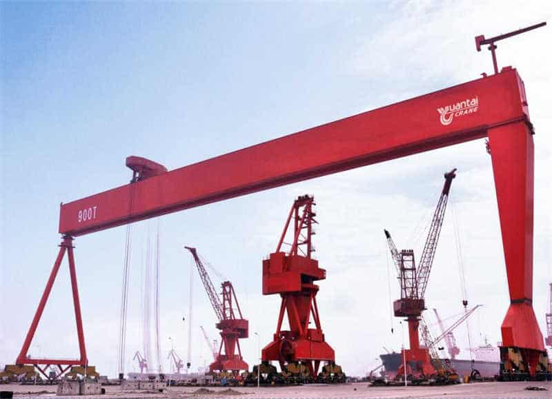
The metal structure of a Type-A Double-Girder Gantry Crane mainly consists of double main girders, two rigid legs, two flexible legs, saddle structures, and upper/lower cross beams forming a portal frame structure. This structural form features high stiffness and good stability, especially suitable for large-span, high-tonnage lifting operations. The overall structural design must consider factors such as load distribution, wind load (for outdoor operation), impact load, etc., to ensure safe and reliable operation under various working conditions.
Structural Composition Framework:
Structure Type Selection: This design adopts a box-type double-girder structure. Compared with truss structures, it offers advantages such as simpler manufacturing processes, easier maintenance, and a more aesthetically pleasing appearance. Although truss structures have the characteristics of light self-weight and good wind resistance, considering the disadvantages of high manufacturing labor and inconvenient maintenance, the box girder design is chosen. The main girder cross-section adopts an optimized box-type structure with necessary longitudinal stiffeners and transverse diaphragms internally to ensure local stability and overall load-bearing capacity.
Double Cantilever Design: This crane adopts a double cantilever structure. The cantilever length on both sides is determined according to actual operational requirements (effective cantilever length on the rigid leg side is 8 meters). The cantilever design can effectively expand the operating range, reduce track laying length, and improve site utilization. The ratio of the cantilever part length to the span needs to be reasonably controlled to avoid excessive internal forces in the main girder or uneven leg pressure due to excessive cantilever length.
Table: Main Components and Functions of the 18/5t-40m Type-A Double-Girder Gantry Crane
| Component | Material | Functional Characteristics | Manufacturing Requirements |
|---|---|---|---|
| Double Main Girders | Q345B Steel Plate | Box section, main load-bearing body, track mounted on it | Weld deformation control, preset camber |
| Rigid Legs | Q345B Steel Plate | Rigidly connected to main girder, withstands bending moment and pressure | Stiffness matching, welding quality |
| Flexible Legs | Q345B Steel Plate | Hinged to main girder, primarily withstands pressure | Allows some deformation, hinge design |
| Saddle Structure | Q345B Cast Steel | Connects main girder and legs, transfers load | Casting quality, fatigue strength |
| Travel Bogies | ZG270-500 | Drives entire machine to run along tracks | Wheel pressure calculation, drive matching |
The main girder, as the most important load-bearing component of the crane, its design directly relates to the safety, reliability, and performance of the entire machine. The 40-meter span double girders in this design must meet the lifting requirements of the 18-ton main hook and 5-ton auxiliary hook, while also considering the impact of the 6-ton trolley self-weight.
Main Girder Cross-Section Design: Adopts a box-section form, composed of upper/lower cover plates, left/right web plates, and internal stiffeners. Box girders have advantages such as high bending and torsional stiffness, good local stability, and mature manufacturing processes. Based on similar design experience, the main girder height is preliminarily determined to be about 2.2-2.5 meters (approximately 1/16-1/18 of the span), and the width about 0.8-1.0 meters. Specific dimensions need to be determined through detailed calculations to ensure strength and stiffness requirements are met.
Main Girder Internal Stiffening: Longitudinal stiffeners and transverse diaphragms are set inside the box girder:
Main Girder Camber Design: To compensate for deflection deformation under load, the main girder requires pre-camber. According to specification requirements, the pre-camber value is generally 1/800-1/1000 of the span. For a 40-meter span, the pre-camber value is approximately 40-50mm, using a parabolic pre-camber curve. The camber design must consider deflection deformation when the trolley is at mid-span, ensuring no significant sag under rated load.
Main Girder Connection Design: When designing main girder segments, transportation and installation conditions must be considered, setting site connection joints. Connection joints typically use high-strength bolt friction-type connections. Joint locations should avoid high-stress areas and have stiffening details. A saddle structure is set at the connection between the main girder and legs, using cast steel components for machining to ensure reliable connection.
Main Girder Calculation Key Points:
Main girder material is selected as Q345B low-alloy high-strength steel. This material has advantages such as high strength, good weldability, and moderate cost, making it a common material for crane metal structures. For high-stress areas, Q390B material can be considered to improve load-bearing capacity.
The leg system of the Type-A Double-Girder Gantry Crane adopts a one-rigid-one-flexible design scheme, i.e., one side is a rigid leg, the other a flexible leg. This design can effectively adapt to deformations caused by temperature changes, load effects, and other factors in large-span structures, preventing the structure from generating excessive additional stress.
Rigid Leg Design:
Flexible Leg Design:
Leg Height Determination: Comprehensively determined based on parameters such as lifting height (14 meters), trolley height, and spreader height to ensure sufficient lifting space. Leg height must also consider the influence of main girder pre-camber to ensure track gradient does not exceed specified values.
Saddle Structure Design: A saddle structure is set at the connection between the legs and the main girder, serving as the force transfer hub. The saddle is usually made of cast steel (e.g., ZG270-500), ensuring matching with the main girder and legs through precise machining. The saddle structure requires detailed stress analysis to avoid stress concentrations.
Leg Calculation Content:
The leg system design must also consider wind load effects, especially for a 40-meter span gantry crane where wind load may become one of the controlling loads. Calculate wind load based on the basic wind pressure of the usage area, considering height variation coefficients and shape coefficients.
Table: Comparison of Rigid Leg and Flexible Leg Characteristics
| Characteristic | Rigid Leg | Flexible Leg |
|---|---|---|
| Connection with Main Girder | Rigid connection (welding or bolting) | Hinged connection (pin) |
| Main Forces Withstood | Bending moment, Shear force, Axial force | Primarily axial force |
| Cross-section Size | Larger, usually equal to main girder width | Smaller, allows some deformation |
| Manufacturing Difficulty | Higher, requires ensuring matching with main girder | Relatively simple |
| Temperature Deformation Adaptability | Poorer | Better |
A complete gantry crane structural design includes not only the metal structure part but also considers the configuration and coordination of various working mechanisms. This design for the 18/5t-40m Type-A Double-Girder Gantry Crane includes three basic mechanisms: hoisting mechanism, trolley travel mechanism, and gantry travel mechanism.
Hoisting Mechanism Design:
Trolley Travel Mechanism Design:
Gantry Travel Mechanism Design:
Electrical Control System:
Safety Device Configuration:
Mechanism Selection Calculation:
Mechanism design must consider duty class matching, ensuring the mechanism’s duty class is not lower than the entire machine’s duty class. For an A5 duty class crane, the mechanism’s duty class is usually M5 (medium usage frequency).
Crane metal structure design must undergo strict calculation verification to ensure strength, stiffness, and stability requirements are met. The structural calculation for this 18/5t-40m Type-A Double-Girder Gantry Crane is based on GB/T3811-2008 “Crane Design Code”, using a combination of traditional mechanical calculations and finite element analysis.
Load Combination Analysis:
Calculation Case Selection:
Main Girder Strength Calculation:
Stiffness Calculation:
Stability Calculation:
Finite Element Analysis:
Use SolidWorks or similar software to build a 3D model for mesh division and boundary condition setting. Analysis content includes:
Connection Calculation:
Wind Resistance Calculation:
Based on similar design experience, the maximum stress of metal components is controlled within 150.8 MPa. The control accuracy of mid-span deflection directly affects equipment safety performance. A safety factor of 1.1-1.3 must be considered during calculation to ensure structural reliability.
The manufacturing quality of a Type-A Double-Girder Gantry Crane directly affects its performance and safety reliability. The structural design of this 18/5t-40m crane must fully consider manufacturability, including various stages such as cutting, forming, welding, and assembly. At the same time, a reasonable installation plan must be formulated to ensure on-site installation quality.
Main Girder Manufacturing Process:
Leg Manufacturing Process:
Welding Quality Control:
Anti-Corrosion Treatment:
Installation Plan Design:
Contact our crane specialists
Send us a message and we will get back to you as soon as possible.