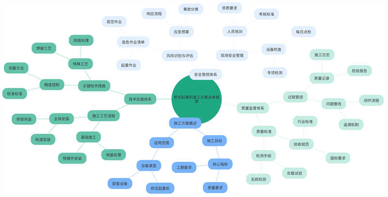
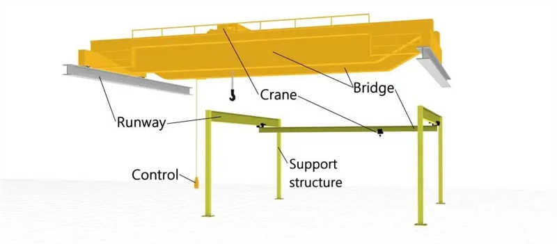
In modern industrial construction, bridge cranes are critical material handling equipment, and their construction quality directly impacts production efficiency and operational safety. A scientific and rational construction plan is essential for ensuring crane performance meets standards and stable operation. This plan encompasses comprehensive management from preliminary preparation to final acceptance, focusing on addressing typical construction challenges such as precision control for the hoisting of large steel structures and the coordination of multi-disciplinary work. Through systematic process design and standardized quality control, we achieve a balance between construction efficiency and safety, laying a solid foundation for subsequent equipment operation and maintenance.
As core material handling equipment within industrial plants, the construction quality of bridge cranes not only directly impacts the smooth operation and efficiency of production lines but is also a critical component in ensuring production safety. Therefore, when developing a construction plan, we must fully consider all factors to ensure a scientific and rigorous construction process. This plan forms a closed-loop management system from preliminary preparation to final acceptance, encompassing three major systems: technical implementation, safety management, and quality supervision. It utilizes a modular construction approach combined with dynamic adjustments to ensure on-time and high-quality project completion.
First, to ensure a safe and smooth construction process, a professional surveying team conducts a comprehensive survey and assessment of the construction site. For foundation bearing capacity testing, static load tests are used to precisely measure the data, ensuring accurate data with millimeter-level precision. This allows for timely identification of foundation problems, enabling effective remediation measures and preventing construction accidents caused by these issues.
For 3D scanning and BIM modeling of the factory space, the surveying team utilizes advanced 3D scanning technology to comprehensively scan the interior and create an accurate BIM model. This BIM model provides a clear understanding of the factory’s internal structure, dimensions, and location, providing a reliable basis for subsequent construction design. Interference between the crane rails and the building structure is also carefully verified to ensure consistent layout and dimensions, avoiding construction difficulties and safety hazards caused by interference.
For environmental assessment, the surveying team focuses on measuring environmental parameters such as humidity and dust concentration in the work area. If environmental parameters do not meet standard requirements, the environmental control plan must be promptly activated and effective measures implemented to ensure that the construction process complies with relevant standards and requirements. This will help improve construction quality and efficiency and protect the health and safety of construction workers.
When forming a construction team, it is essential to ensure that team members possess the appropriate special equipment installation qualifications, which is a mandatory qualification. The staffing model should be a “1+3+5” echelon: one registered mechanical engineer provides overall technical guidance, three certified crane operators are responsible for key construction steps, and five assemblers form a mobile team to participate in construction. This configuration ensures technical support and safety during the construction process.
To ensure that the construction team has the necessary safety awareness and operational skills, all team members must undergo training. This training should include theoretical knowledge of GB6067 “Safety Regulations for Lifting Machinery” and simulated lifting operation tests. After the training, a rigorous assessment should be conducted to ensure that all team members have mastered the relevant knowledge and skills, with a 100% pass rate. This will improve the safety and efficiency of the construction process and reduce the risk of accidents.
In terms of material procurement, it is necessary to ensure that steel structure components meet the GB/T14405 acceptance standard. A third-party UT inspection report must be provided for main beam welds to ensure weld quality meets requirements. For key components such as electric hoists and busbars, a “one-item, one-code” traceability system is implemented to ensure that each component can be traced back to the manufacturer and date of manufacture. These components must complete a 72-hour no-load run test before arriving on-site to ensure stable and reliable performance.
In terms of tool configuration, the torque wrench range must be carefully considered. Torque wrenches are commonly used tools during construction, and their range directly impacts construction quality and efficiency. Therefore, it is important to select a torque wrench with an appropriate range based on actual needs and ensure that its accuracy and reliability meet requirements. Additionally, other necessary construction tools and equipment, such as cranes and welding machines, must be equipped as needed. The adequacy of these tools and equipment will directly impact the smooth progress of the entire construction process.
Table: Construction Materials and Equipment List (Steel Structure Installation)
| Category | Specific projects | Technical standards/requirements | Quality control measures | Pre-entry inspection requirements | Supplier qualification requirements |
| Steel structure components | Main beam | GB/T14405 acceptance standard | Third-party UT test report (weld) | Dimensional tolerance ≤±2mm | Possess special steel structure production license |
| Lifting equipment | Electric hoist | JB/T9008.1 safety specification | 72-hour no-load operation test | Brake response time <0.5 seconds | ISO9001 certification |
| Electrical system | Conductor rail | GB/T7251.1 insulation standard | One-item-one-code traceability management | Insulation resistance ≥ 10MΩ | 3C compulsory certification |
| Measuring tools | Torque wrench | JJG707 Metrology Verification Procedure | Regular calibration (accuracy ±3%) | Measuring range covers 50-300N·m | CMA Metrology Certification |
| Safety equipment | Fall arrester | GB24543 fall protection standard | Impact test certificate | Maximum braking distance ≤ 0.2m | EU CE certification |
Table: Construction staffing and training requirements
| Post | Qualification Requirements | Number of personnel | Training content | Assessment Criteria | Scope of Responsibilities |
| Registered Mechanical Engineer | First-class construction engineer (mechanical and electrical major) | 1 | BIM modeling review/hoisting plan review | The plan passed expert review | Full process technical guidance |
| Certified crane operator | Q2 Special Equipment Operation Certificate | 3 | GB6067 Safety Regulations/Simulated Lifting | Practical test 100% qualified | Key process operations |
| Assembler | Welder certificate/height work certificate | 5 | Steel structure assembly process/emergency evacuation | Theoretical exam ≥90 points | Component installation and auxiliary work |
| Quality Inspector | UT/MT Level 2 Testing Qualification | 2 | Weld Inspection Standards/Measurement Instruments | False positive rate <1% | Process quality monitoring |
| Safety Supervisor | Registered Safety Engineer | 1 | Emergency plan drills/hazard identification | Excellent drill evaluation | Full safety inspection |
Concrete pouring is crucial during foundation construction. We used C30 grade commercial concrete to ensure that the strength and durability of the concrete met the design requirements. To ensure the installation accuracy of embedded parts, we used a total station positioning system to control the verticality deviation of the embedded parts to within 1/1000, thus ensuring the quality and stability of the embedded parts. During the curing period, we implemented dual temperature and humidity monitoring to ensure that the concrete was cured under optimal temperature and humidity conditions. Once the concrete strength reached the design requirements, we conducted a settlement test, loading the foundation with a hydraulic jack and measuring its settlement. If the settlement did not exceed 2mm within 24 hours, the foundation was considered qualified and could proceed to the next step.
Bridge installation is a critical step in the entire project. We used a segmented hoisting process. After the bridge was hoisted into place, a laser theodolite was used to accurately calibrate the bridge’s mid-span camber to ensure it met the design requirements. The measured value should be within the range of (0.9-1.4) S/1000 (S represents the span), ensuring both bridge stability and operational requirements. High-strength bolts at the end beam connections are tightened in three stages, with a final torque tolerance of ±5%. This ensures proper tightening and prevents deformation or damage to the bridge due to overtightening or undertightening. Track installation complies with JB/T6392 standards, with a joint clearance of no more than 2mm to ensure accurate and stable track installation.
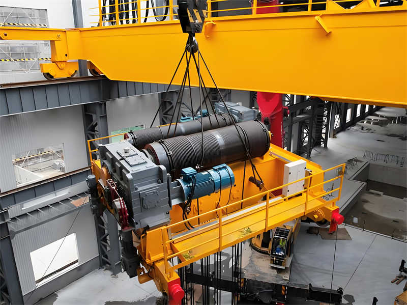
The installation of the hoisting mechanism is crucial to the operation of the entire equipment. We use a double gauge method to align the reducer and motor coupling, ensuring radial displacement does not exceed 0.1mm, thereby ensuring the stability and reliability of the hoisting mechanism. The wire rope winding system is equipped with an anti-slip device to effectively prevent the wire rope from slipping during operation. At least three safety loops are retained on the drum to ensure sufficient buffer space in emergency situations. During a no-load test run, the braking slippage must not exceed 1/100 of the rated speed to ensure a sensitive and reliable braking system.
The installation and commissioning of the electrical system is directly related to the normal operation and safety of the equipment. We strictly test the insulation resistance of the power busbar according to specifications, achieving a value greater than 10MΩ to ensure electrical safety. The trolley travel mechanism is equipped with an audible and visual alarm device to enhance operational safety. The control system undergoes 100 simulated load tests, and all limit switches must achieve 100% accuracy to ensure control system stability and reliability. The lightning protection grounding system has a surge grounding resistance of ≤4Ω, effectively preventing lightning strikes and static electricity hazards.
To ensure safe production, we have established a strict safety management system, implementing a “three-ticket, three-system” management mechanism. This includes a lifting operation ticket, a confined space ticket, and a temporary power use ticket, as well as a shift handover system, a patrol inspection system, and a confirmation system. The implementation of these systems effectively prevents safety accidents, ensuring employee safety and the normal operation of the company. Furthermore, we hold daily morning safety meetings and use smart helmets to record work processes. The data is uploaded to a cloud-based monitoring platform in real time for continuous monitoring and tracking of work progress.
We use the LEC method to quantitatively assess six types of hazards, including falls from height and impacts. Based on the assessment results, specific emergency plans are required for processes with a D value greater than 160. For the main beam lifting process, we have implemented a four-level protection system: fall prevention nets, lifelines, double-hook safety harnesses, and emergency air cushions. These measures effectively reduce safety accidents, ensuring employee safety and the normal operation of the company.
We attach great importance to employee safety education and training, using VR simulation training to cover all high-risk scenarios, including emergency response to wire rope breaks and handling sudden power outages. These training sessions not only enhance employee safety awareness but also strengthen their ability to respond to emergencies. Furthermore, we conduct monthly “blind drills” to ensure that the time from alarm activation to complete evacuation must not exceed three minutes, ensuring that employees can react quickly and take appropriate measures in emergencies.
During the construction process, implementing the “three inspections and one verification” system is a critical step in ensuring project quality. First, teams should strictly adhere to a self-inspection system to ensure that every process and every step complies with construction specifications. Second, teams should conduct mutual inspections to promptly identify and correct potential quality issues. Third, dedicated quality inspectors should be assigned to conduct specialized inspections of key areas and processes to ensure effective quality control at all critical links. After completing the “three inspections,” the team must submit the acceptance results to the supervisor for review. Only after the supervisor confirms compliance can the next step be initiated. To further strengthen quality control, witnessed sampling is implemented at critical control points, such as the re-testing of the torque coefficient of high-strength bolted connections. According to relevant regulations, the torque coefficient of high-strength bolted connections must be re-tested before installation to ensure the safety and reliability of the connection. During re-testing, each set of test pieces must consist of at least eight sets to ensure the accuracy and representativeness of the data.
During the acceptance process, the main control project strictly adhered to the relevant requirements of TSGQ7015, “Type Test Rules for Hoisting Machinery.” This rule covers all performance indicators and safety requirements for hoisting machinery, ensuring the safe and efficient operation of the equipment after commissioning. For general projects, GB50231, “General Specification for Construction and Acceptance of Mechanical Equipment Installation Projects,” was implemented. This standard details the construction process, quality requirements, and acceptance standards for mechanical equipment installation projects. To fully verify the performance and stability of the equipment, load tests were conducted in three levels: first, a 1.25x static load test was conducted to check the equipment’s load-bearing capacity and stability under static conditions; then, a 1.1x dynamic load test was conducted to simulate the dynamic load conditions experienced during actual operation; finally, the equipment was required to operate at rated load for eight consecutive hours to verify its performance and durability under prolonged high loads. Through these three levels of testing, the equipment’s performance was comprehensively assessed to ensure it met design requirements and safety standards.
To effectively address various quality issues that arise during construction, a defect classification management system was implemented. Defects are categorized into three categories: A, B, and C, based on their severity and scope of impact. For Category A defects, which represent major issues seriously impacting project quality and safety, a stop-work order must be issued immediately, and rectification efforts must be organized until the problem is completely resolved. For Category B defects, a closed-loop treatment plan must be developed and implemented within 48 hours. For Category C defects, they must be incorporated into the PDCA cycle to continuously improve construction quality. Detailed video footage must be retained for all processes involving rework, and a special rectification report must be prepared, detailing the issue, treatment measures, implementation process, and effectiveness evaluation, providing experience and lessons learned for subsequent construction.
Table: Construction Quality Control and Acceptance Standards Table
| Quality control | Implementation content | Standards/Specifications | Key indicators/requirements | Treatment measures | Relevant documents/basis |
| Three-inspection system | Team self-inspection, mutual inspection, and dedicated quality inspection | Construction specification requirements | 100% coverage of key parts and processes | After submitting to the supervisor for review, proceed to the next process | _ |
| Witness sampling | Re-test of torque coefficient of high-strength bolt connection | Industry Standards | Each group of specimens ≥ 8 sets | Installation is prohibited if re-inspection fails | _ |
| Acceptance of main control projects | Lifting machinery performance and safety acceptance | TSGQ7015 | All indicators met | Class A defects must be stopped immediately for rectification | Rules for Type Test of Lifting Machinery |
| General project acceptance | Mechanical equipment installation process acceptance | GB50231 | Process compliance ≥95% | 48-hour closure for Class B defects | General Specifications for Installation and Acceptance of Mechanical Equipment |
| Load test | 1.25 times static load/1.1 times dynamic load/8 hours rated load | Design Specifications | No structural damage | Class C defects are included in PDCA improvements | Special rectification report retention |
| Defect Management | Classification and treatment of A/B/C defects | Quality Management System | Class A 0 tolerance | Video materials + special reports | PDCA cycle system |
Table: Construction quality defect classification and processing table
| Defect level | Judgment criteria | Response time limit | Processing Flow | Verification method | Record requirements |
| Category A | Affecting structural safety or main functions | Stop work immediately | Comprehensive rectification → third-party re-inspection | Destructive testing + expert evaluation | Full process image + rectification report |
| Category B | Partial quality does not meet the standards but can be repaired | ≤48 hours | Formulate a plan → Closed-loop processing | Special inspection + supervision confirmation | Comparison photos before and after rectification |
| Category C | Minor workmanship defects | Improvements as planned | PDCA cycle optimization | Sampling review + data analysis | Improve record keeping |
| Rework process | Does not meet acceptance criteria | Corresponding to defect level | Re-inspection → keep samples for future reference | Double sampling inspection | Image data archiving |
| Witness sampling failure | Material/component performance does not meet standards | within 24 hours | Exit processing + tracing the source | Third-party laboratory retesting | Defective product disposal form |
When developing the construction schedule, we used the Critical Path Method (CPM) to create a detailed four-level plan. This method helps us accurately identify the project’s critical path—the sequence of tasks that have the greatest impact on the project’s completion date. In practice, we accurately timed each key milestone down to the day. For example, the “track installation completion date” was set as a key milestone for the entire project, and its completion date serves as a direct benchmark for subsequent processes. To ensure flexibility and adjustability in the plan, we included a 15% margin when assigning resources. Furthermore, considering the potential adverse effects of construction during the rainy season, we increased our manpower reserve by 20% to ensure adequate construction progress despite adverse weather conditions.
The BIM5D platform compares the construction plan with the actual progress in real time. If the deviation exceeds 5%, the system automatically triggers an alert. Upon receiving the alert, we implement fast tracking to optimize the construction process. For example, by rationally arranging parallel work for electrical piping and mechanical installation, we can effectively shorten the critical path, thereby accelerating the overall construction progress. Furthermore, we flexibly adjust resource allocation and labor scheduling based on actual monitoring results to achieve more efficient and practical construction management.
To address potential delays, we developed a fishbone diagram analysis model. This model systematically analyzes and thoroughly analyzes six common delay factors, such as equipment arrival delays and extreme weather, helping us develop targeted mitigation strategies. Furthermore, to quantify the relationship between delay costs and rush costs, we implemented a rush rate calculation model. When the cost of delay exceeds the additional expense of rushing, we decisively implement a two-shift construction system, increasing manpower to shorten the critical path and thereby mitigate the losses caused by delays. This scientific and systematic management approach not only improves construction efficiency but also ensures the project is completed smoothly and on schedule.
Contact our crane specialists
Send us a message and we will get back to you as soon as possible.