Single-girder bridge cranes, as an essential material handling equipment, are widely used in workshops, warehouses, and open-air storage yards. They offer advantages such as simple structure, light weight, and low cost. This article systematically introduces the key structural design elements of single-girder bridge cranes, including main girder design, outrigger and end girder structure, hoisting mechanism configuration, electrical control system, and overall optimization solutions. By thoroughly analyzing the design principles, calculation methods, material selection, and safety considerations of each component, this article provides engineering designers with a comprehensive set of design ideas and technical references. Furthermore, this article explores the application of modern design methods such as finite element analysis in crane design, as well as the reflection of emerging trends such as intelligent and green crane design. This article aims to help readers understand the core technologies and future development trends of single-girder bridge crane design.
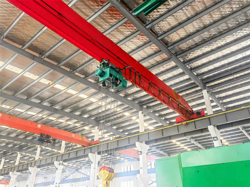
A single-girder bridge crane is a lightweight lifting device typically consisting of a main girder and two rigidly connected end girders forming a bridge structure. It reciprocates on an overhead track to lift materials. This type of crane is suitable for applications with a rated lifting capacity of 0.5 to 5 tons and a span of 4.5 to 16.5 meters. Its operating temperature generally ranges from -20°C to 40°C. It is widely used for material handling in machinery manufacturing, assembly workshops, warehouses, and other locations. Compared to traditional double-girder bridge cranes, single-girder structures offer advantages such as light weight, low cost, and compactness, making them particularly suitable for applications with strict space and cost requirements.
Historically, my country’s bridge crane technology made significant progress in the 1950s and 1960s, with the widespread adoption of box-type structures in the 5-50 ton low-capacity series and the 75-250 ton high-capacity series. With technological advancements, the design concepts and technical parameters of single-girder bridge cranes have been continuously optimized. The box-girder bridge structure of modern cranes plays a significant role in reducing labor intensity, saving manpower, lowering construction costs, and improving labor productivity. It has become a key piece of equipment for achieving engineering mechanization and production automation.
A single-girder bridge crane primarily consists of four major components: a metal structure, a hoisting mechanism, a running mechanism, and an electrical control system. The metal structure includes load-bearing components such as the main beam and end beams. The hoisting mechanism is responsible for vertical lifting and lowering of objects, typically powered by an electric hoist. The operating mechanism enables horizontal movement of the crane along the track. The electrical control system coordinates the movements of these mechanisms to ensure safe and reliable operation. Modern single-girder bridge cranes offer three different modes of operation: ground control, control room control, and remote control. The control room features two door designs, one for the end and one for the side, greatly facilitating user selection and operation.
Working class is a crucial parameter in crane design, determined by both the crane’s operating level and the load conditions. In single-girder bridge crane design, the overall working class and the working class of each mechanism must be determined based on actual operating conditions. This directly influences material selection, structural design, and component configuration. Generally speaking, single-girder bridge cranes are suitable for less frequent operations and are not suitable for lifting molten metal, hazardous materials, or precision lifting operations requiring high installation accuracy.
As the core load-bearing component of a single-girder bridge crane, the main girder’s design quality is directly related to the safety, reliability, and performance of the entire crane. The main girder must withstand multiple forces, including lifting loads, deadweight, inertia, and wind loads, and must ensure sufficient strength, rigidity, and stability. Under long-term loads, the main girder structure must be free of plastic deformation, cracks, or other forms of failure. Elastic deformation must also be controlled to ensure the crane’s operational accuracy and stability.
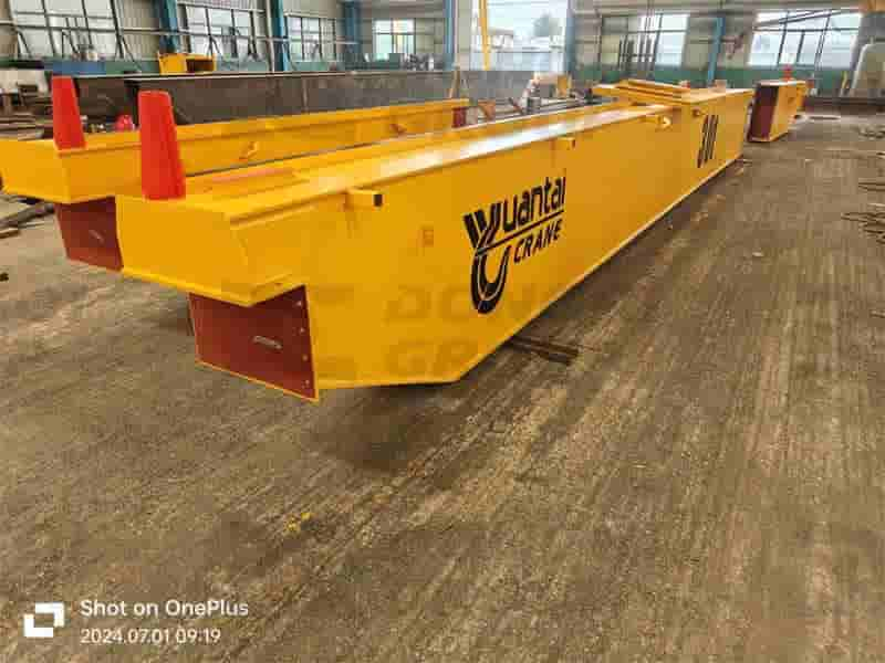
Single-girder bridge crane main girders primarily come in two types: I-beam and box-section. I-beam main girders are typically welded together using ordinary hot-rolled I-beams and U-shaped channels. They offer simple manufacturing and low cost, making them suitable for light-duty cranes with small tonnage and short spans. For cranes with larger lifting capacities or longer spans, box-section girders are more suitable. Composed of upper and lower deck plates welded together with two vertical webs, the box-section girder offers a closed cross-section and excellent bending and torsional resistance. It is the most common bridge structure used in bridge cranes both domestically and internationally. Box beams can be equipped with longitudinal and transverse stiffeners to further enhance local stability and overall load-bearing capacity, making them suitable for lifting loads of 5 to 50 tons.
In actual engineering design, the selection of main beam cross-sections requires a comprehensive consideration of factors such as lifting load, span, operating system, and manufacturing cost. Research has shown that the overall performance advantages of box beams are more pronounced when lifting loads exceed 5 tons or spans exceed 16.5 meters. Furthermore, box beams facilitate internal wiring and accessory installation, and offer a cleaner and more aesthetically pleasing appearance. These factors have made box beams the mainstream choice for modern single-girder bridge cranes.
Main beam length and span are the first key parameters to be determined during design. Span refers to the distance between the main beam’s support points, which directly affects the crane’s operating range and structural stress conditions. Based on actual application data, the main beam length of a 10-ton single-girder bridge crane is typically between 10 and 20 meters, while larger cranes may exceed 30 meters. The actual length of the main beam is generally 1.5-2 meters longer than the span to accommodate end beam connections and buffer device installation. The optimal span must be determined during design based on the user’s workshop layout and usage requirements, while also considering coordination with the location of the factory columns to ensure reliable crane track support.
Determining cross-sectional dimensions is a key aspect of main beam design. For box-shaped main beams, parameters such as the width and thickness of the upper and lower decks, and the height and thickness of the webs, require detailed calculations. The upper deck, in addition to bearing overall bending stress, also bears the localized compressive stresses generated by the hoist’s wheel pressure, and is therefore typically slightly thicker than the lower deck. The web height is generally 1/12 to 1/18 of the span to ensure sufficient rigidity and control deflection within the allowable range. Main beams are typically designed with a uniform height for ease of manufacturing. For larger lifting loads, an upward camber design (with a preset camber of L/1000) can be employed to offset downward deflection under load and improve operational performance.
Material selection has a decisive impact on main beam performance. The main girder of a single-girder bridge crane is generally made of Q235B or Q345B steel. The latter offers higher strength but requires more stringent welding procedures. The yield strength of Q345B steel can reach 345 MPa, approximately 46% higher than the 235 MPa of Q235B. Under equivalent load conditions, this can reduce structural weight by approximately 15-20%, but at a correspondingly higher cost. Material selection should be comprehensively considered during design based on the crane’s operating class, operating environment, and economic efficiency. For operating temperatures below -20°C, the material’s low-temperature toughness should also be considered to avoid the risk of cold-induced brittle fracture.
Main girder strength calculations include overall bending strength, localized compressive strength, and strength verification under complex stress conditions. Overall bending strength is calculated based on the maximum bending moment, taking into account the combined effects of deadweight and hoisting loads. For a 5-ton, 34-meter span single-girder bridge crane, the maximum bending stress at the mid-span section of the main girder should be less than the material’s allowable stress (approximately 140 MPa for Q235B). Localized crush strength primarily targets the upper deck area where the electric hoist wheels act. Localized stress and deformation caused by wheel pressure must be calculated to avoid excessive crushing or fatigue cracking.
Stiffness calculation primarily controls the deflection of the main beam under rated load. The allowable deflection for single-girder bridge cranes is typically specified as 1/700 to 1/1000 of the span. For example, for a 34-meter span main beam, the allowable deflection is approximately 34-48.5 mm. Insufficient rigidity can lead to unstable crane operation and difficulty climbing the electric hoist, compromising operational safety and service life. Modern design methods often employ finite element analysis (FEM) to conduct detailed stress and deformation analysis of the main beam. This accurately predicts structural response under complex loading conditions and verifies the rationality of the design. FEM analysis results show that the maximum stress point of an optimized main beam structure typically occurs in the mid-span lower deck or the upper deck at the supports. This maximum stress should be below the material yield point, leaving a sufficient safety margin.
Table: Typical values of main beam design parameters for single-girder bridge cranes
| Parameter | Typical value or range | Remark |
| Lifting capacity | 0.5-5 ton | Special design up to 10 tons |
| Span | 4.5-16.5m | Up to 34 meters |
| Operating temperature | -20℃~40℃ | Low temperature environments require special materials |
| Main beam section height | Span 1/12~1/18 | The box beam has a smaller value |
| Allowable deflection | Span 1/700~1/1000 | For those who require high running stability, select a smaller value. |
| Material yield strength | ≥235MPa(Q235B) | Or≥345MPa(Q345B) |
The outriggers and end beams form the support and travel system of a single-girder overhead crane and are crucial components of its structural design. The end beams, located at each end of the main girder, are connected to the main girder via high-strength bolts or welding, forming a complete bridge structure. The outriggers support the entire bridge structure and transfer loads to the track and building structure. The design of the outriggers and end beams must meet strength, rigidity, and stability requirements, while ensuring smooth and precise crane operation and avoiding undesirable phenomena such as “three-legged” operation.
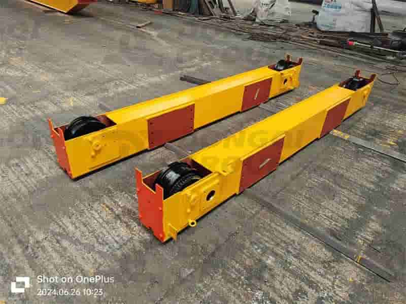
The end beam is a key component connecting the main girder and the wheel assembly, bearing the bending loads from the main girder and the horizontal inertia forces during crane operation. In single-girder overhead cranes, the end beams typically utilize a box section or a composite section formed by welded steel plates, with internal reinforcing ribs to enhance local rigidity and stability. The end beams are generally the same height as the main girder or slightly shorter, creating a harmonious appearance and balanced load distribution. Angular bearing housings are installed at each end of the end beams to accommodate the wheel assembly and drive unit. This modular design facilitates manufacturing, installation, and maintenance. The connection method between the main beam and the end beam has a significant impact on the overall performance of the crane. Common connection methods include flange bolting and welding. Flange bolting uses load-bearing flanges and standard bolts to secure the main beam to the end beam, offering the advantages of easy installation and transportation. However, bolts may loosen under dynamic loads and require regular inspection. Welding creates a rigid joint with good integrity, but also exhibits high residual stresses and requires high welding process requirements. In modern designs, high-strength bolted connections are increasingly used, ensuring connection strength while reducing welding distortion, making them particularly suitable for medium- and large-tonnage cranes.
The wheel load calculation and drive system layout are key considerations in end beam design. Wheel load directly impacts the design of the track and building structure. Typically, the wheel load on all four wheels must be evenly distributed, with the maximum wheel load not exceeding the load-bearing capacity of the track and building structure. The drive system can be either centralized or distributed. The centralized drive eliminates the long drive shaft, resulting in a simpler structure and easier maintenance, making it the mainstream choice for modern single-girder bridge cranes. Appropriate reinforcement structures are required within the end beam to withstand the concentrated loads transmitted by the wheels and prevent local buckling or excessive deformation of the end beam web.
Outriggers are the supporting structure of a crane, and their stability is essential for its proper operation. The outriggers of single-girder overhead cranes can be categorized as rigid or flexible, depending on their structural form. Rigid outriggers form a rigid connection with the main girder and end beams, capable of withstanding vertical and horizontal forces. Flexible outriggers allow for a certain amount of horizontal movement, adapting to structural expansion and contraction caused by temperature fluctuations and improving load-bearing conditions. In single-girder structures, a dual-rigid outrigger design is commonly used. This design is simple and easy to manufacture, making it suitable for applications with narrow spans and moderate operating temperature fluctuations.
The outrigger height should be determined based on the required workshop clearance and lifting height. Outriggers that are too high will reduce overall rigidity, while those that are too low will limit the crane’s effective working space. A case study of a single-girder overhead crane in Zhoushan shows that for a 10-ton crane with a 15-meter main girder length, the outrigger height is typically between 6 and 8 meters. The specific value should be calculated based on the track elevation and the required lifting height. Outriggers are often box-shaped in cross-section, with internal diaphragms to enhance torsional resistance. External access platforms and ladders can be installed for easy maintenance and inspection.
The connection between the outriggers and the foundation must ensure reliable load transfer and allow for a certain degree of adjustment. Common connection methods include anchor bolts and rail pressure plates. Anchor bolts are suitable for new construction, as bolts can be pre-buried during civil construction, resulting in a rigid connection. Rail pressure plates are suitable for retrofit projects, as they can be installed on existing tracks and offer easy adjustment. Regardless of the method used, outrigger verticality and good wheel-rail contact must be ensured to avoid wheel overhang or uneven wheel load distribution.
Outrigger and end beam designs must be verified for stability and overturning resistance to ensure the crane will not become unstable under various operating conditions. Stability calculations include both static and dynamic stability. Static stability primarily considers the combined effects of the rated load, wind load, and grade load; dynamic stability accounts for the inertia forces generated by sudden starting or braking of the hoisting mechanism. The calculation should select the most unfavorable load combination to verify the load-bearing capacity and stability of the outriggers and end beams.
Anti-overturning calculations verify the crane’s safety under lateral loads, typically requiring an anti-overturning safety factor of at least 1.5. Factors such as the crane’s deadweight, rated load, maximum operating wind pressure, and seismic loads (for high-intensity areas) must be considered during the calculation. For single-girder overhead cranes used outdoors, wind load is often the controlling factor, and appropriate measures should be taken during the design to reduce the wind resistance coefficient, such as using guardrails and platforms with high air permeability. Furthermore, track installation accuracy can affect crane stability. Design requirements call for a track slope of no more than 0.3%, and a track gauge deviation within ±5mm.
The hoisting mechanism is the core component of a single-girder bridge crane, performing load lifting and lowering operations. Its design directly impacts the crane’s operating efficiency, safety, and reliability. Single-girder bridge cranes typically utilize an electric hoist as the hoisting mechanism. This hoist integrates components such as a drum, motor, brake, reducer, and hook, resulting in a compact structure, light weight, and easy operation. The hoisting mechanism design must meet technical requirements for rated lifting capacity, lifting height, operating speed, and other parameters, while complying with relevant safety standards and regulations to ensure stable operation under various operating conditions.
The electric hoist is the most commonly used hoisting mechanism for single-girder bridge cranes. Depending on the structure, it can be categorized as either a wire rope hoist or a chain hoist. LD-type electric single-girder bridge cranes typically utilize a CD1 or MD1 wire rope hoist. Rated lifting capacities range from 0.5 tons to 10 tons, meeting most light and small lifting needs. When selecting an electric hoist, factors such as the lifting capacity, lifting height, operating level, and operating environment should be considered to ensure sufficient safety margins and a low failure rate over its lifecycle.
The mounting method of the electric hoist on a single beam affects the overall load distribution. Common mounting methods include suspended and supported. Suspended electric hoists are suspended from the lower flange of the main beam via running wheels. This simplifies the structure and facilitates installation, but places greater local pressure on the beam. Supported electric hoists are fixed to the side of the main beam via brackets, providing a more balanced load distribution but a more complex structure. The design should determine the appropriate mounting method based on the main beam cross-section and electric hoist model, calculate the wheel load distribution, and ensure that the local stability of the main beam meets the requirements.
The design of the electric hoist’s trolley must consider the wheel load distribution and drive method. The trolley is typically equipped with four running wheels, two of which are active wheels, driven by an electric motor through a speed reducer. The wheels are typically made of cast steel or alloy steel, heat-treated for improved wear resistance. The trolley frame utilizes a welded steel plate structure to ensure sufficient rigidity and prevent deformation that affects smooth operation. The trolley design also requires safety accessories such as buffers, limit switches, and anti-collision devices to ensure safe and reliable operation.
The drum is the core component of the electric hoist, responsible for winding and guiding the wire rope. Drum design requires consideration of parameters such as diameter, length, rope groove size, and wall thickness. The drum diameter directly affects the bending stress of the wire rope and is generally required to be no less than 16-20 times the wire rope diameter to maximize wire rope life. The rope groove design should ensure that the wire ropes are neatly arranged to avoid tangling and skipping. Drums are typically made of cast iron or cast steel, though modern designs also utilize rolled and welded steel plates to reduce weight and maintain quality control.
Wire rope selection is a critical step in hoist mechanism design. The appropriate type and specifications of wire rope must be selected based on the rated load, safety factor, and operating environment. Single-girder bridge cranes typically use 6-strand or 8-strand wire ropes with either a fiber core or a metal core. The former offers excellent flexibility, while the latter is heat-resistant and extrusion-resistant. The safety factor of a wire rope is generally no less than 5, with higher requirements for personnel lifting or hazardous material handling. The design also requires calculating the number of wire rope layers wrapped around the drum, typically no more than three, to ensure neat rope arrangement and sufficient rope capacity.
The fixed end treatment and guide design of the wire rope are also crucial. The fixed end is typically secured to the drum using a pressure plate or wedge joint, requiring a secure, reliable, and easy-to-check design. The guide pulley should have a sufficient diameter and smooth grooves to reduce bending stress and wear on the wire rope. The pulley design must consider the ratio to balance the lifting speed and driving force requirements. Single-girder bridge cranes typically use a two- or three-ratio pulley.
The hook directly bears the working load, making its safety paramount. Single-girder bridge cranes typically use forged hooks made of high-quality low-carbon alloy steel, heat-treated and surface-treated to enhance strength and wear resistance. The hook opening should ensure ample working space, typically two to three times the standard diameter. The rated lifting capacity of the hook must match the crane’s capacity and be clearly marked. Overloading is prohibited. Finite element analysis is often performed on hooks in modern designs to verify stress distribution and safety.
The hook’s suspension system includes a pulley assembly, crossbeam, bearings, and lubrication system. The suspension system must be designed to ensure even load distribution and flexible rotation, avoiding eccentric loading and binding. The crossbeam should have sufficient rigidity and strength to withstand vertical loads perpendicular to its axis and remain stable during the hook’s raising and lowering, without shaking or deformation. The pulley assembly should be designed to ensure smooth vertical movement of the hook. Appropriate pulley configurations, such as single-row or multi-row pulleys and single-sided or double-sided pulleys, can be used to accommodate different operating scenarios and requirements.
For bearing design, high-precision, low-friction bearings, such as rolling or sliding bearings, should be selected to ensure stable rotation under long-term high-load operation, reduce wear, and extend service life. Furthermore, an effective lubrication system should be established to provide a regular and quantitative supply of lubricating oil or grease to reduce friction and prevent performance degradation or failure due to overheating. To ensure safety and reliability, key suspension components should be equipped with overload protection devices that automatically cut off power or sound an alarm when the load exceeds a set value, effectively preventing accidents caused by overload. Furthermore, they should include features that facilitate installation, maintenance, and repair, such as adjustable connections and easily observable status indicators.
Contact our crane specialists
Send us a message and we will get back to you as soon as possible.