As the core equipment of modern industrial material handling, the bridge structure design of the beam crane directly affects the performance and safety of the whole machine. The single-beam bridge structure occupies an important position in small and medium-tonnage lifting applications due to its light weight, low cost and compact structure. This article will systematically introduce the whole process of single-beam bridge structure design, covering key contents such as type selection, parameter determination, structural design, strength calculation, manufacturing process and optimization direction, and provide a comprehensive design reference for engineering and technical personnel.
As an important type of material handling equipment, the single-beam bridge crane is widely used in many industrial fields such as machinery manufacturing, assembly workshops, warehousing and logistics due to its simple structure, light weight and good economy. Its bridge, as the core load-bearing component of the crane, is directly related to the safety, reliability and working performance of the whole machine. The single-beam bridge is usually composed of a main beam and two end beams. The main beam bears all the hoisting loads and transmits the load to the plant track structure through the end beams. Its design needs to comprehensively consider multiple requirements such as strength, stiffness, stability and practical economy.
From the perspective of structural evolution, the single-beam bridge has gone through a development process from truss beam to steel beam and then to box beam. Although the early truss beam structure was light in weight, it had a complex manufacturing process and poor torsional performance, and has been gradually eliminated. Modern single-beam bridges mainly adopt two forms: steel beam and box beam. Among them, steel beam (usually I-beam or H-beam) has a simple structure and low manufacturing cost, which is suitable for light-duty working occasions with small tonnage and small span; while the box beam is welded into a closed section by upper and lower flange plates and two side webs. It has outstanding advantages such as high bending and torsional rigidity and good overall stability, and has become the mainstream choice for medium and large single-beam cranes.
Compared with the traditional double-beam bridge, the single-beam bridge structure has significant space advantages, the height of the whole machine is small, and it can better adapt to the low factory environment. At the same time, the single-beam bridge has a light weight, which can reduce the load-bearing requirements of the factory structure and save infrastructure costs. However, the single-beam structure also has some inherent limitations, such as relatively low horizontal stiffness, weak torsion resistance, and the problem of slanted walking when the trolley is running. These characteristics need to be specifically considered in the structural design.
According to the different main beam structure forms, modern single-beam bridges can be divided into the following categories: first, standard I-beam beam structure, which is mostly used for light and small cranes below 5t and with a span of less than 18m; second, special-shaped steel reinforced beam structure, which increases the load-bearing capacity by adding reinforcement plates or trusses to the lower flange of the main beam; third, box-type welded beam structure, which is suitable for large tonnage or large span occasions; fourth, European optimized beam structure, which adopts a special box-type variable cross-section design to make the structure more compact, improve the lifting height and space utilization.
Bridge structure design is a systematic project, which must comprehensively consider the technical parameters of the crane (such as lifting weight, span, working level, etc.), operating environment conditions, material process factors and manufacturing costs. The design process usually adopts a “top-down” approach, first determining the overall layout and main parameters according to the use requirements, then carrying out specific design work such as structure selection, load analysis, strength and stiffness calculation, stability verification, and finally completing detailed structural design and manufacturing process design. The entire design process needs to comply with relevant national standards and industry specifications, such as GB/T 3811-2008 “Crane Design Specifications” and JB/T 1306-2008 “Electric Single-Girder Crane”, to ensure that the design results are safe, reliable and economically reasonable.
The design of a single-beam bridge structure is a creative work based on the actual needs of the project and must be based on fully clear design inputs and technical parameters. Design preparation is like the foundation of a building, which determines the scientificity and reliability of the entire design process. Before starting the design, engineers need to comprehensively collect and analyze various original data, which not only directly affect the structural form and size parameters of the bridge, but also are related to the final safety and performance of the crane.
The determination of the original technical parameters is the first step in the design work. According to the search results, the key original design parameters include: rated lifting capacity (usually 1-20t), crane span (common range 8-25m), lifting height (generally 3-30m), working level (mostly A3-A5), working speed of each mechanism (lifting speed is usually double speed 8/0.8m/min, trolley running speed 20-30m/min, trolley running speed 30-45m/min), etc.. It is worth noting that the lifting capacity and span are the most critical factors in determining the cross-sectional size of the main beam and must be taken as the core consideration parameters. For example, compared with a 5t single-beam crane, the main beam height and plate thickness of the LD-10 single-beam crane (lifting capacity 10t) need to be significantly increased to cope with greater bending stress and shear stress. At the same time, the working level reflects the load characteristics and frequency of use of the crane, which directly affects the fatigue life calculation and safety factor selection of the structure.
In actual engineering applications, the determination of the span needs to take into account the plant structure and process layout. Designers must accurately measure the distance between the center lines of the crane tracks, rather than simply using the plant column spacing. According to practice, the bending moment caused by the deadweight of the main beam will increase significantly with every 1m increase in span, especially in large spans of more than 15m, where this effect is more obvious. The case in the search results shows that when a double-beam crane with a span of 25.5m was designed, the main beam height reached 1/14-1/18 of the span, which is much larger than the 1/20-1/25 ratio for small spans. Although this is a double-beam case, it is also of reference value to single-beam design, indicating the strict requirements of large spans on structural stiffness.
Load calculation is the basis of bridge structure design, and all possible stress conditions must be considered comprehensively. The loads borne by the bridge can be divided into two categories: vertical load and horizontal load. Vertical loads include dead load (dead weight of main beam, end beam, electric hoist and electrical equipment) and live load (rated lifting load and dynamic load coefficient); horizontal loads mainly include inertia force generated by crane start-up and braking, lateral force during operation deflection, and accidental collision load, etc.. The introduction of dynamic load coefficient is particularly important, which reflects the impact effect of the lifting mechanism on the structure when it is started. The value is generally 1.1-1.3, which varies according to the working level. In a design case, when calculating a 50/10t double-beam crane, not only the main lifting load was considered, but also the structural response under the auxiliary lifting condition was verified. This comprehensive consideration of various working conditions is also applicable to single-beam design.
Material selection is an important decision in the design preparation stage. Modern single-beam bridges generally use Q235B or Q355B steel. These two materials have achieved a good balance in strength, plasticity and economy. The yield strength of Q235B is 235MPa, with excellent welding performance and relatively low price, which is suitable for small-tonnage cranes. The yield strength of Q355B (formerly Q345) is increased to 355MPa, which can effectively reduce the deadweight of the structure in large-tonnage or large-span situations. Although the welding process requirements are slightly higher and the cost is increased, it is often more advantageous in overall optimization. When a single-beam crane project in Zhoushan adopted a box-beam design, the weight of the main beam was reduced by about 15% by selecting Q355B material, while meeting the stiffness requirements. Material selection also needs to consider environmental factors, such as the need to use weathering steel or increase anti-corrosion measures in coastal areas.
With technological progress, the European crane concept has had a positive impact on traditional single-beam design. The European single-beam bridge adopts an optimized box-type structure, placing the hoisting wheel in the middle or lower part of the main beam, which significantly improves the space utilization in the height direction. This structure expands the hoist wheel spacing, increases the track contact length, and effectively improves the stress concentration problem on the electric hoist’s travel track and the horizontal swing problem perpendicular to the main beam direction. The search results mentioned that a certain European design “changed the traditional I-beam into a box-type welded structure, increasing the lifting space by more than 20%”^[5]. This design concept is particularly suitable for renovation projects with limited lifting height and is worth considering when determining design parameters.
Table: Reference values of main original parameters for single-beam bridge design
| Parameter Category | Typical value range | Remark |
| Rated lifting capacity | 1-20t | Key factors determining the cross section of the main beam |
| Working span | 8-25m | Actual distance from track centerline |
| Working level | A3-A5 | Impact on safety factors and fatigue calculations |
| Lifting height | 3-30m | Related to plant clearance |
| Main beam material | Q235B/Q355B | Select by load and span |
| Electric hoist model | CD/MD Type | Influence of wheel pressure distribution and local stress |
After comprehensively collecting and analyzing various original parameters, the designer needs to preliminarily determine the bridge structure form and main dimensions. The selection of box-type single beams and I-beam single beams needs to comprehensively consider the lifting capacity, span, working level and manufacturing cost. Practice has shown that for lifting capacities above 10t or spans above 16m, the box-type beam has more obvious advantages in stiffness and strength. The main beam height is usually 1/14-1/22 of the span, and the width is about 1/3-1/4 of the height. This ratio can ensure sufficient bending resistance and is conducive to controlling the deadweight of the structure. The next step of design calculation will conduct detailed verification and necessary adjustments to these preliminarily selected parameters to ensure the safety, reliability and economic rationality of the structure.
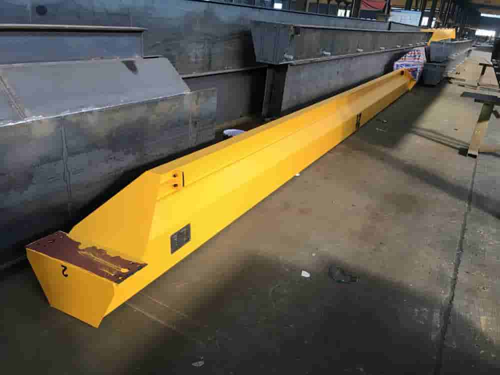
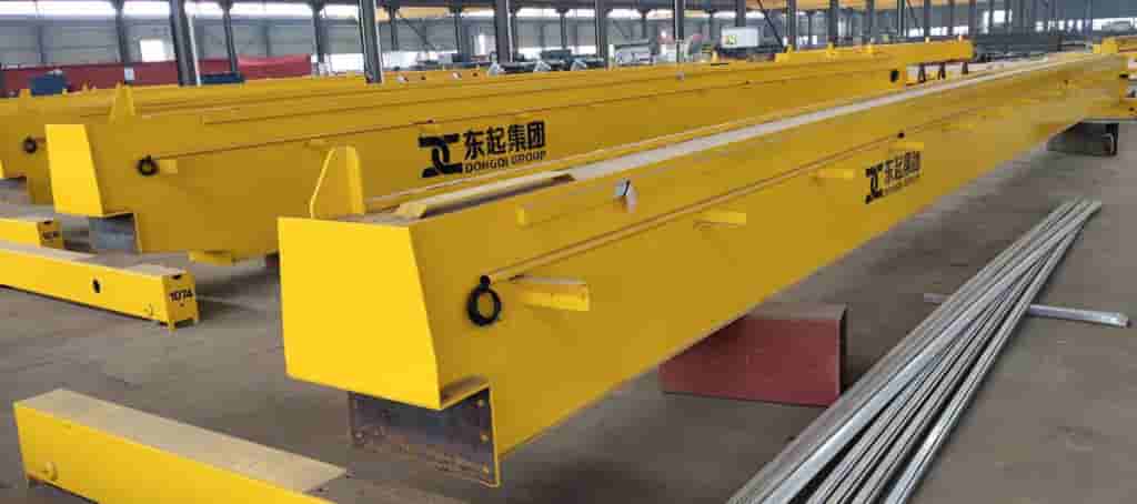
As the core load-bearing component of a single-beam bridge crane, the main beam’s structural design directly determines the safety and working performance of the entire machine. The main beam needs to bear the concentrated wheel pressure from the electric hoist, the lifting load, and the distributed load generated by its own weight. It must ensure that it has sufficient strength, rigidity, and stability under various working conditions. The main beams of modern single-beam cranes are mainly box beams and steel beams. Each type has its own unique structural characteristics and applicable scope. When designing, it is necessary to make a reasonable choice based on specific parameters and usage requirements.
The box beam structure is welded by upper and lower flange plates and two side webs to form a closed section. This structure has significant advantages in bending and torsion resistance. According to the search results, the main beam of Zhoushan single-beam bridge crane adopts a typical box-type design, which can provide sufficient strength and rigidity to effectively resist distortion and lateral pressure. The cross-sectional size of the box beam can be flexibly adjusted according to the load conditions. It is usually designed as a narrow section (smaller width) to adapt to the operating requirements of the electric hoist. A certain number of transverse and longitudinal stiffening ribs are usually arranged inside the box beam to prevent the web from buckling and improve the local bearing capacity. In the steel structure design of a 5t single-beam crane, a transverse stiffening rib is arranged every 1.5m inside the box beam, and a longitudinal stiffening rib is arranged under the wheel track of the electric hoist. This design detail is crucial to prevent local instability.
I-beam is another common form of main beam for single-beam cranes, which is made of hot-rolled steel or welded I-beam. The main advantages of I-beam are simple structure, easy manufacturing and low cost. It is particularly suitable for light-duty working occasions with small tonnage (generally less than 5t) and small span (usually less than 12m). However, I-beam has obvious deficiencies in torsional performance and horizontal stiffness. When the electric hoist is running under eccentric load, it is easy to cause the main beam to twist and bend horizontally. The search results mentioned that the main beam of the traditional electric single-beam crane has the problems of “small lifting space” and “stress concentration on the walking track of the electric hoist”. To improve this situation, a horizontal truss or reinforcement plate can be added to the lower flange of the I-beam to increase its lateral stiffness, but this will increase the deadweight of the structure and an economic trade-off needs to be made.
In recent years, the European optimized main beam structure has gradually gained market favor. This structure changes the traditional lifting wheel placed above the main beam to a middle or lower position, greatly improving the space utilization in the height direction. The European electric single-beam crane main beam design mentioned in the search results “improves the space utilization in the height direction and improves the problem of small lifting space of the traditional electric single-beam crane main beam”. This structure effectively improves the stress concentration problem and horizontal swing phenomenon by expanding the lifting wheel spacing and increasing the track contact length. The European main beam mostly adopts a box-type variable cross-section design welded with steel plates, which achieves a compact appearance while ensuring structural strength, and increases the lifting height by more than 20% compared with the traditional design, which is particularly suitable for renovation projects with limited plant clearance.
The determination of the cross-section size of the main beam is the core content of the structural design, which needs to be comprehensively calculated based on the strength, stiffness and stability requirements. The main geometric parameters of the box-type main beam include beam height, beam width, upper and lower flange plate thickness, and web plate thickness. According to the design experience in the search results, the main beam height is usually 1/14-1/22 of the span, and the width is about 1/3-1/4 of the height. For example, for a 10t single-beam crane with a span of 16m, the main beam height is designed to be 700mm (about 1/22 of the span) and the width is 280mm. This ratio ensures sufficient bending stiffness while facilitating the installation and layout of the electric hoist.
In addition to bearing the overall bending stress, the upper flange plate also needs to support the running track of the electric hoist, so its thickness is usually greater than the lower flange plate. The width of the upper flange plate should ensure the stable installation of the track, and is generally 30-50mm wider than the bottom of the track. The lower flange plate mainly bears tensile stress, and its thickness can be determined based on calculation, but should not be less than 6 mm to ensure local stability. The height of the web is the same as the main beam height, and its thickness must meet the shear resistance requirements and local stability requirements, usually 6-12 mm. When the web height-to-thickness ratio exceeds the limit (such as when Q235 steel is greater than 80), transverse stiffeners must be installed to prevent buckling. In a Zhoushan single-beam crane project, the box-type main beam adopts a closed section of “upper and lower flange plates and web plates welded on both sides”, and the strength and stiffness requirements are met by reasonably configuring the plate thickness.
Table: Empirical reference values of box-type single-beam main beam section parameters (Q235B material)
| Lifting capacity(t) | Span(m) | Beam height(mm) | Beam width(mm) | Upper flange thickness (mm) | Bottom flange thickness (mm) | Web thickness (mm) |
| 3-5 | 10-16 | 400-550 | 200-280 | 8-10 | 6-8 | 5-6 |
| 10 | 10-18 | 550-750 | 250-350 | 10-12 | 8-10 | 6-8 |
| 16-20 | 14-22 | 700-900 | 300-400 | 12-14 | 10-12 | 8-10 |
In order to compensate for the deflection deformation under the action of deadweight and external load, the main beam of the crane usually needs to be set with prefabricated camber. The search results mentioned that during the design, it is necessary to determine “the various internal force loads, stability and camber of the main end beam and check them one by one” according to the “Crane Design Manual”. In theory, the camber value should be equal to the deflection value caused by the rated load at the mid-span, which is generally 1/1000-1/800 of the span. In actual operation, considering the manufacturing process and measurement convenience, the camber curve is often designed as a quadratic parabola or arc, and the maximum camber at the mid-span is controlled within the range of L/700-L/1000 (L is the span). For example, for a main beam with a span of 16m, the reasonable camber is about 16-23mm. Excessive camber will affect the operating performance of the electric hoist, especially when approaching the end beam, a “climbing” phenomenon may occur; insufficient camber will cause the mid-span to sag under the rated load, affecting the use effect.
The calculation of camber needs to consider the weight distribution and stiffness characteristics of the main beam. The traditional approximate calculation method is to simplify the main beam into a simply supported beam under uniform load, and its mid-span camber can be estimated according to the formula f=5qL^4/384EI (q is the uniform load concentration, E is the elastic modulus, and I is the section moment of inertia). Modern design uses more finite element analysis technology, which can more accurately simulate the actual load conditions and boundary conditions and obtain more accurate camber curves. The steel structure design of a 5t single-beam crane uses finite element analysis to “calculate the bending stress of the I-beam under the load of the main beam, as well as the main beam stiffness of the crane under dynamic and static conditions”. This analysis method based on computer-aided engineering greatly improves the design accuracy and reliability.
The design of the main beam structure also needs to pay attention to the local reinforcement structure, especially at the wheel rail support part of the electric hoist, the connection part with the end beam, and the concentrated load action point. The electric hoist track is usually made of square steel or light railway rail, which is fixed to the center of the upper flange plate by continuous welding or intermittent welding. The rail joints should have a smooth transition to avoid impact when the electric hoist is running. The stress in the connection area between the main beam end and the end beam is complex, and it is usually necessary to increase the web thickness or set additional stiffening ribs. Although these detailed designs may seem small, they have an important impact on the safety and service life of the entire machine and must be given full attention during the design stage.
End beam and main end beam connection design
As an important component of the single-beam bridge structure, the end beam has multiple key functions: on the one hand, it supports the main beam and transfers all loads to the trolley track; on the other hand, it ensures the smooth operation of the crane along the track, and at the same time, it also resists the horizontal force and deflection moment generated during operation. The design quality of the end beam directly affects the operating performance and safety reliability of the whole machine, and must be given sufficient attention. A reasonable end beam structure must not only have sufficient strength and rigidity, but also consider factors such as the connection method with the main beam, the layout of the wheel group, and the convenience of installation and maintenance.
The end beam structure mainly depends on the crane’s lifting capacity and the layout of the operating mechanism. According to the search results, the end beam of a single-beam bridge crane usually adopts a box-type welded structure, which is welded into a closed section by steel plates, which can ensure good torsional resistance and horizontal rigidity. The cross-sectional height of the end beam is generally 1/2-2/3 of the main beam height, and the width is determined according to the wheel group size and buffer installation requirements. The design of the end beam of a certain LD electric single-beam crane shows that its cross-sectional height is about 350-500mm and its width is 250-350mm. It is equipped with transverse stiffening ribs inside to improve local stability.
The design of the end beam length needs to take into account two factors: one is to ensure sufficient support width to ensure stable operation of the bridge frame, and the other is to control the total length of the whole machine to adapt to the limitations of the factory building. Usually, the length of the end beam is 1.5-2 times the height of the main beam, which can be appropriately increased for large-tonnage cranes. Buffer mounting seats are provided at both ends of the end beam, which must ensure sufficient strength and energy absorption capacity. The trolley wheel group is installed under the end beam. The wheel diameter is determined according to the wheel pressure calculation, usually 250-500mm. The wheel material is mostly cast steel or alloy steel. Forged steel wheels are used when the working level is high.
The internal structure design of the end beam is equally important. A transverse partition needs to be set inside the box-type end beam to transmit the concentrated force of the wheel. The spacing between the partitions is generally not more than 1.5 times the beam height. The connection between the end beam and the main beam is complex and usually requires special reinforcement. In a design case, two transverse stiffeners and one longitudinal stiffener were set in the connection area between the end beam and the main beam, which effectively dispersed the connection stress.
Contact our crane specialists
Send us a message and we will get back to you as soon as possible.