As an important equipment in modern industrial production and logistics transportation, single-girder bridge cranes are widely used in workshops, warehouses, open-air storage yards and other places due to their simple structure, low cost and flexible use. This paper will comprehensively discuss the structural design points of single-girder bridge cranes, conduct a systematic analysis from the main beam design, end beam structure, lifting mechanism, operation system to electrical control, and combine modern design methods and engineering practice to provide a reference basis for related design work.
Single-girder bridge cranes are a light lifting equipment and an important member of the bridge crane family. Its basic working principle is to realize material handling operations in three-dimensional space through a bridge structure that spans above the workshop or building and cooperates with a lifting trolley that moves along the main beam. This type of crane usually consists of a main beam and two end beams rigidly connected to form a bridge structure. The lifting mechanism often uses an electric hoist as a lifting device. In terms of technical parameter range, the applicable lifting capacity of single-girder bridge crane is generally 0.5-20 tons, among which 5-ton and below models are the most common; the applicable span is usually between 4.5-16.5 meters, but can reach 34 meters or even larger under special design conditions; the working environment temperature range is wide, and it can adapt to environmental conditions of -35℃ to +40℃ according to different design standards. This wide range of application enables it to meet the needs of most industrial occasions.
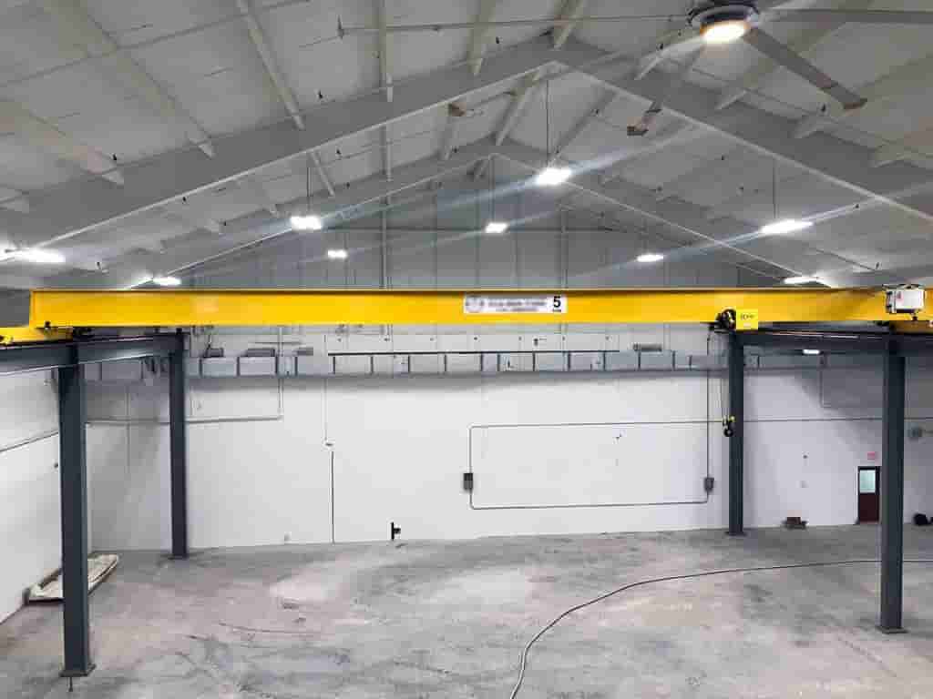
Compared with double-girder bridge cranes, single-girder structures have obvious structural characteristics: first, they have lighter weight, which reduces the load requirements of the plant structure; second, they have low manufacturing costs and significant economic benefits; third, they have small height dimensions, which increase the effective lifting space; and finally, they are easy to install and maintain, which reduces the cost of use. However, the performance of single-girder structures under lifting capacity and large span conditions is usually not as good as that of double-girder structures, which requires sufficient demonstration and calculation in the design stage.
From the perspective of structure, a single-girder bridge crane is mainly composed of metal structure parts (including main beam, end beam and connecting parts), lifting mechanism (electric hoist or winch system), operating mechanism (trolley operation and trolley operation) and electrical control system. Among them, the metal structure accounts for about 60%-70% of the total weight of the machine and is the key guarantee for the safety and reliability of the crane. With the development of modern industrial technology, the design concept of single-girder bridge cranes is also constantly updated. Traditional design mainly focuses on the strength and stiffness of the structure, while modern design methods pay more attention to the optimization, lightweight and intelligentization of the structure. The introduction of finite element analysis technology enables designers to evaluate structural performance more accurately, and the application of various optimization algorithms further improves material utilization. At the same time, the application of new technologies such as remote control technology and frequency conversion control has greatly expanded the functional boundaries and user experience of single-girder bridge cranes.
As the core load-bearing component of a single-girder bridge crane, the rationality of its design directly determines the safety, reliability and economy of the entire machine. The main beam needs to withstand the combined effects of the wheel pressure from the hoisting trolley, deadweight load, wind load (outdoor type) and various dynamic loads. Therefore, during the design process, multiple requirements such as strength, stiffness and stability must be fully considered.
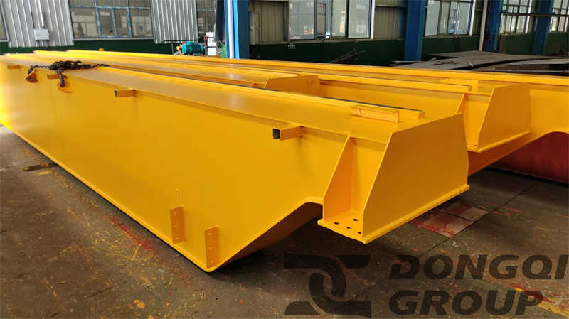
The common cross-section forms of the main beam of a single-girder bridge crane are mainly I-beam section, U-shaped channel and I-beam combination section and box section. The I-beam section has a simple structure, is easy to manufacture and has low cost. It is suitable for light-duty cranes with small tonnage (usually less than 5 tons) and small span (within 10 meters). The U-shaped channel and I-beam combined section significantly improves the bending and torsional resistance of the main beam by adding a U-shaped channel steel to the lower flange. It is suitable for medium tonnage (5-10 tons) and medium span (10-16.5 meters) applications. For larger tonnage (up to 20 tons) or larger span (over 16.5 meters), a box section beam is required. This structure is welded from upper and lower cover plates and two vertical webs and has the best mechanical properties and stability. The selection of the section is mainly based on factors such as lifting capacity, span, working level and economy. In design practice, cranes of 5 tons and below mostly use I-beams or combined sections, while cranes of 5 tons and above tend to use box sections. It is worth noting that the U-shaped channel and I-beam combined section is widely used in actual engineering. By welding the U-shaped channel steel to the lower flange of the I-beam, it not only enhances the overall stiffness, but also provides an ideal electric hoist running track surface, while solving the problem of easy wear of the lower flange of the I-beam.
The strength calculation of the main beam must take into account a variety of load combination conditions, including vertical load (self-weight load, lifting load), horizontal load (inertia load, lateral force of deflection operation) and dynamic load coefficient, impact coefficient, etc.. Among them, the dynamic load coefficient φ6 reflects the vertical dynamic load effect generated by the crane during operation. For small and medium-sized single-beam cranes, it is generally taken as 1.1-1.3; the impact coefficient φ1 considers the dynamic influence of the lifting mechanism on the structure when it is working, and is usually taken as 1.0-1.2. The calculated stress should include the overall bending stress of the main beam, the local wheel pressure stress and the composite stress to ensure that the maximum stress is less than the allowable stress of the material and has a certain safety margin. In modern design practice, finite element analysis has become an effective tool for verifying the strength of the main beam. Studies have shown that the maximum stress of a properly designed main beam should be lower than 0.6-0.8 times the yield limit of the material.
Stiffness control is also a key indicator for main beam design, including static stiffness and dynamic stiffness. Static stiffness is usually measured by the deflection value under the rated load. The specification requires that for single-beam bridge cranes, the vertical static deflection of the main beam under the rated load should not be greater than 1/700-1/800 of the span. Dynamic stiffness involves the natural frequency of the structure. To avoid resonance, the first-order vertical vibration frequency of the main beam should be controlled above 2Hz. In actual engineering, for main beams with larger spans (such as more than 16 meters), the stiffness condition is often more difficult to meet than the strength condition. At this time, it is necessary to increase the stiffness by increasing the section height, setting the camber or adopting prestressing technology.
The manufacturing process of the main beam has a significant impact on its performance. Welding is the main process method for manufacturing main beams, but the control of welding deformation and residual stress is crucial. For composite section beams, automatic submerged arc welding is usually used to ensure welding quality; for box beams, attention should be paid to the welding sequence and process parameters of the four main welds to prevent excessive deformation. The preset camber is a key link in the manufacture of main beams. Generally, a prefabricated camber is set at 0.9/1000-1.4/1000 of the span to offset the deflection under the action of deadweight and load. In addition, the shape and position tolerances such as the waviness of the web of the main beam and the horizontal deflection of the cover plate must also be strictly controlled to ensure uniform stress and smooth operation of the structure. In terms of material selection, the main beam usually uses Q235B or Q345B steel. The former is lower in cost and the latter is higher in strength, which helps to reduce the weight of the structure. The yield strength of Q345B steel can reach 345MPa, which is about 50% higher than that of Q235B. Under the same load conditions, it can reduce the amount of steel used by 15%-20%, but its welding process requirements are higher and the cost is also increased accordingly. For cranes used outdoors or in corrosive environments, the weather resistance of the material must also be considered. If necessary, weather-resistant steel or additional anti-corrosion measures should be used. After the material is selected, it must be strictly inspected and accepted in accordance with the relevant specifications to ensure that the chemical composition, mechanical properties and process performance meet the design requirements.
Table: Comparison of main beam cross-sections of single-girder bridge cranes
| Section type | Applicable tonnage | Applicable span | Advantage | Shortcoming | Cost |
| I-beam | 0.5-5t | 4.5-10m | Simple structure and easy manufacturing | Low stiffness and poor torsional resistance | Low |
| I-beam + U-shaped channel | 1-10t | 10-16.5m | Good rigidity and wear-resistant track surface | Large amount of welding work | Medium |
| Box beam | 5-20t | >16.5m | Good strength and stiffness, high stability | Complex manufacturing process | High |
As an important component of the bridge of a single-girder bridge crane, the end beam has multiple functions, including connecting the main beam, transferring loads to the supporting structure, and guiding the entire machine to run along the track. The quality of the end beam design directly affects the operating performance, stability and service life of the crane. Compared with the main beam, although the end beam is relatively less stressed, its structure is complex and requires the integration of multiple components such as wheel sets, buffer devices, and drive devices. Therefore, it also needs to be given full attention in design.
The typical end beam structure of a single-girder bridge crane mainly includes two types: box end beam and composite section end beam. The box end beam is welded into a closed section by steel plates. It has the characteristics of high torsional stiffness and good structural stability. It is suitable for medium and large tonnage cranes or higher working level occasions. The composite section end beam is mostly made of channel steel or I-beam and connecting plates. It has a simple structure, is easy to manufacture, and has low cost. It is commonly used in small tonnage and light-duty cranes. Regardless of the form, the height of the end beam is usually designed to coordinate with the height of the main beam end to form a smooth force flow transmission path.
Functional integration consideration is one of the key points of end beam design. The end beam needs to be installed with a variety of components such as wheel sets, drive motors, reducers, brakes, buffers and limit devices. These components need to be arranged reasonably during design to ensure sufficient installation space and maintenance channels. For example, the drive wheel should be arranged on the side close to the center line of the main beam to reduce the wheel pressure difference; the buffer installation height needs to match the track end stop; the limit switch should be reliably triggered and easy to adjust. In addition, transmission components such as drive shafts and couplings are often arranged inside the end beam, so appropriate observation holes and inspection covers need to be designed.
The choice of connection method has an important impact on the overall performance of the crane. The connection between the main beam and the end beam of a single-beam bridge crane mainly includes flange bolt connection and welding connection. Flange bolt connection is achieved by setting a flange with high-strength bolts at the end. The advantage of this method is that it is easy to transport and install on site, and the verticality of the main beam and the end beam can be adjusted. The disadvantage is that the connection stiffness is slightly lower, which is suitable for small and medium-sized cranes. Welding connection provides higher stiffness and strength, which is conducive to force flow transmission, but requires higher welding technology and is inconvenient to transport. It is mostly used for large-tonnage or large-span cranes. In recent years, some designs have adopted a mixed connection method, that is, adding fillet welds on the basis of flange connection, combining the advantages of both.
The design of connection details requires special attention to the transmission path and stress concentration issues. For bolt flange connection, a load-bearing flange with flange is usually used. The flange bears vertical shear force, and the bolt mainly bears horizontal force and moment. The number of bolts is generally not less than 8, and the diameter is determined according to calculation but is usually not less than M16. The material should be high-strength bolts such as grade 8.8 or grade 10.9. The flange contact surface needs to be finely machined to ensure a tight fit. If necessary, a positioning stop can be designed to ensure installation accuracy. For welded connections, appropriate groove forms and welding sequences should be designed to control welding deformation. It is best to perform stress relief treatment after welding. Regardless of the connection method, the stress state in the connection area is relatively complex, and it is recommended to use finite element analysis for detailed evaluation.
The calculation of end beam strength needs to consider a variety of working conditions, especially the additional horizontal force generated when the crane runs at an angle or hits the end stop of the track on one side. The calculated load should include the maximum vertical wheel pressure, horizontal lateral force and dynamic load coefficient. The vertical static stiffness of the end beam usually requires that its deflection under the maximum wheel pressure does not exceed 1/1500 of the distance between the centers of the two wheels. In addition, the local stress at the connection between the end beam and the main beam also needs to be checked. If necessary, reinforcing ribs or local thickening can be added. For end beams with drive mechanisms, the section weakening effect at the point where the drive shaft passes through also needs to be verified.
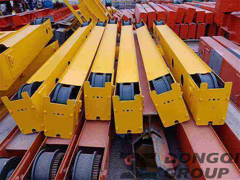
The optimization of wheel arrangement is crucial to the operating performance of the crane. Single-beam bridge cranes usually use four wheels for support, two of which are driving wheels and two are driven wheels. The wheel diameter is selected according to the maximum wheel pressure, and double-flange wheels are generally used to enhance the anti-derailment capability. The determination of wheel spacing (base distance) requires comprehensive consideration of operational stability and structural compactness, and is usually taken as 1/4-1/6 of the span and not less than 1/3 of the vehicle body length. Too small a base distance will lead to unstable operation of the crane and easily cause “rail gnawing” phenomenon; while too large a base distance will affect the turning radius (for curved rails) and increase the weight of the structure. The wheel material is usually ZG340-640 cast steel or alloy forged steel, and the surface hardness should reach HB300-380 to improve wear resistance and service life.
Table: Comparison of connection methods between main beam and end beam of single-girder bridge crane
| Connection method | Advantage | Shortcoming | Applicable occasions | Design Points |
| Flange bolt connection | Easy to transport and install, adjustable | Low stiffness and complex structure | Small and medium-sized cranes with limited on-site installation conditions | High-strength bolts, precision-machined flange surface, anti-loosening measures |
| Welding connection | High rigidity and simple structure | Inconvenient to transport, high welding stress | Large tonnage crane, factory installed directly | Groove design, welding sequence, stress relief |
| Hybrid Connections | Stiffness and adjustability | Complex process and high cost | Special requirements | Bolt preload control, weld quality |
The hoisting mechanism and operating mechanism constitute the motion system of the single-girder bridge crane, which directly determines the crane’s operating performance and work efficiency. An excellent design not only needs to meet basic functional requirements, but also needs to consider multiple factors such as energy consumption, reliability, and maintenance convenience. Modern single-girder bridge cranes widely adopt modular design concepts, optimizing the design of the hoisting mechanism and the operating mechanism as relatively independent subsystems^[4][7][16].

The selection of electric hoists is the core content of the design of the hoisting mechanism of a single-girder bridge crane. As an integrated hoisting device, the electric hoist integrates components such as the motor, reducer, drum, brake, and hook into one, with the advantages of compact structure, easy installation, and simple maintenance. Common domestic CD1 (normal speed) and MD1 (slow speed) wire rope electric hoists, as well as chain electric hoists, can be selected according to needs. When selecting, the main factors to consider are rated lifting capacity, lifting height, working level, and special environmental requirements. For example, for situations requiring precise positioning, an electric hoist with variable frequency control can be selected; for explosion-proof environments, an explosion-proof electric hoist must be selected.
The layout of the lifting mechanism directly affects the stress state of the main beam. The traditional layout is that the electric hoist is suspended on the lower flange of the main beam for operation. This method is simple and direct, but increases the torsional load of the main beam. Another method is that the electric hoist is supported by a trolley and runs on both sides of the main beam. This method has better stability but a more complex structure. For large-tonnage single-beam cranes, the latter method is more suitable. When designing, attention should also be paid to the clearance distance between the electric hoist and the end beam to ensure that there is no interference at the extreme position. Usually, a safety distance of 200-300mm is left. In addition, the power supply introduction method of the electric hoist (trolley line or cable drag chain) also needs to be reasonably selected according to the stroke length and environmental conditions.
The design of wire rope and hook is a key link in the safety of lifting mechanism. The selection of wire rope should meet ANSI, DIN or GB standards, and the minimum breaking force should be determined according to the maximum working load. The safety factor is generally not less than 5. The winding method of wire rope on the drum should minimize the number of bends. Single-layer winding is usually adopted. Multi-layer winding can be adopted when necessary, but the load capacity needs to be reduced. The hook material should be made of high-quality low-carbon killed steel such as DG20, which is made by heat treatment after forging. Cast hooks are prohibited. If the opening deformation of the hook exceeds 15% of the original size or the torsional deformation exceeds 10°, it must be scrapped to ensure safe use. For special materials such as steel plates, coils, etc., electromagnetic suction cups or special lifting devices can be used. At this time, attention should be paid to the power supply introduction and control system design.
The trolley operating mechanism drives the single-girder bridge crane to move along the factory track. Its design needs to consider factors such as driving force, starting acceleration and braking performance. Common driving methods are centralized drive and separate drive. Modern single-girder cranes mostly adopt separate drive mode, that is, a set of drive devices are set on each end beam on both sides, and synchronization is achieved through electrical control. The drive unit usually consists of an electric motor, a brake, a reducer and a wheel group, which is called a “three-in-one” drive device. It has the advantages of compact structure and easy installation. The motor power calculation needs to consider the running resistance (including rolling resistance, slope resistance, wind resistance and inertia resistance, etc.). Generally, the motor power of small-tonnage single-girder cranes is in the range of 0.4-2.2kW.
The trolley operating mechanism refers to the drive system for the electric hoist to move along the longitudinal direction of the main beam. For suspended electric hoists, the trolley is mostly driven by electricity, with the motor driving the wheels through the reducer to run on the lower flange of the main beam. The trolley wheels are usually made of nylon or steel, and the wheel pressure should be controlled within the load-bearing capacity of the main beam. The trolley running speed is generally around 20m/min. Too high a speed will cause swaying problems during start-up and stop. In the design of the trolley frame, anti-derailment devices and buffer devices need to be set to prevent the trolley from rushing out of the main beam in extreme cases. For large-tonnage cranes, a double-wheel trolley or a balance beam structure can be used to disperse the wheel pressure.
Track selection and installation have an important impact on the performance of the operating mechanism. The trolley track of a single-beam bridge crane usually uses P-type railway track or QU-type crane special track, while the trolley track mostly uses the lower flange of I-beam or special track steel. The track installation must ensure the straightness of the top surface (usually ≤1/1000 span), the gauge tolerance (±3-5mm) and the elevation difference of the tracks on both sides (≤1/1000 base distance). There are two ways to fix the track: pressure plate fixing and direct bolt fixing. In either case, the track should be allowed to have a certain amount of thermal expansion and contraction margin. The track joints should have a smooth transition, and the joint gap is generally 2-4mm, which needs to be appropriately increased in cold areas. In order to ensure the smooth operation and safety of the operating mechanism, the installation accuracy and stability of the track are crucial. During the installation process, relevant specifications and standards must be strictly followed to ensure that the geometric dimensions of the track meet the requirements to reduce running resistance and prevent equipment damage caused by uneven or twisted tracks.
For the trolley track of a single-girder bridge crane, P-type railway track or QU-type crane-specific track is usually used. These tracks have high strength and stability and can withstand the load and vibration generated by the crane during operation. At the same time, their shape and size are also optimized to meet the operating requirements of the crane. Trolley tracks are often constructed from the lower flange of an I-beam or specialized rail steel. These materials offer excellent toughness and wear resistance, ensuring stability and safety during trolley operation. Furthermore, trolley track installation must be carefully considered in conjunction with the gantry track to ensure coordinated operation of the entire crane system.
During track installation, critical dimensions such as top surface straightness, track gauge tolerance, and track elevation difference must be accurately maintained. The accuracy of these parameters directly impacts the performance and safety of the operating mechanism.
Contact our crane specialists
Send us a message and we will get back to you as soon as possible.