One of the most critical pieces of equipment in a steel mill is the ladle crane, but too many steel mill operators don’t pay enough attention to the design and procurement of the crane. Correct selection of crane materials, components and specifications is crucial to ensuring high levels of productivity and an efficient steelmaking shop.
However, during the procurement process, heavy equipment such as turbines, boilers and to some extent pumps and valves are given more emphasis, while ladle cranes are neglected. Ladle crane purchasing decisions are made hastily, with little scientific thinking applied, so the technical specifications only roughly meet the application requirements.
Additionally, budget constraints often make matters worse. Since ladle cranes are typically procured after a factory’s caster, steel shop, and furnace, there is little money left for procurement, limiting appropriate crane specifications.
To ensure efficient and correct commissioning, procurement, design, manufacture and installation of ladle cranes, collaboration between manufacturer and customer is crucial.
For smaller mills, price is always an important factor in the procurement process and total funding for expansion needs to be carefully balanced.
However, cost cutting at this stage is likely to have a knock-on effect on the plant’s productivity in future years, whether through higher and more frequent repairs and maintenance than necessary, or a shortened life cycle due to being unsuitable for the task at hand.
In the long run, whether it is a 3m ton rolling mill or a 5m ton rolling mill, a crane is required. If a factory wants to ensure the highest level of efficiency, price cannot be the driving factor in the purchasing process.

There are several concepts to consider when selecting a ladle crane. India adopts IS-4137, while international markets recommend FEM and CMAA standards. The FEM standard has clear advantages as it reduces the size of the wheels while optimizing the size of the hook. Of all the available standards for ladle crane design, FEM is the most suitable standard for several reasons.
First, since wheel load calculations for cranes do not use average loads, wheel optimization is actually possible. This design standard allows for accurate comparisons of wheel and rail dimensions.
In addition to detailed guidance on how to check fatigue and accurately select ropes and rope drums, the classification of each available mechanism is clearly explained, allowing design teams to well understand the various options before them.
Looking at ladle cranes for 3 million ton or 5 million ton steel plants, there are five important areas that must be considered in the crane design.
The first, and arguably most important, is the drive system. Most modern steel mills use variable voltage variable frequency (VVVF) drives instead of the traditional slip ring motor concept.
The motors will be standard AC squirrel cage motors requiring no maintenance, while the absence of rotor contactors and rotor cables means less complexity.
To further reduce the number of complexities, overload protection, undervoltage protection and on/off operation are built-in, so external contactors and protective relays are not required.
Continuously variable speed from minimum to maximum speed also means any speed setting is possible, even micro-speeds between 5% and 100% without requiring any additional hardware and allowing for smooth movement.
Another aspect of ladle crane design that can reduce jerky operation is reducing starting current. Start-up current is lower than traditional direct-on-line (DOL) start, improving operation and saving power consumption.
Features such as electrical braking reduce wear on brake shoes and linings compared to simple mechanical braking, meaning less mechanical fatigue on crane components, extending the life cycle of its mechanical components.
Other features such as tandem control functionality with good RPM control, as well as feedback options to facilitate tandem control, parameter display and diagnostic display on the LCD, can also be used while the crane is online, thus reducing downtime. Moving to the second point of note in ladle crane design, fail-safe brakes should always be imported from reputed suppliers. While domestic brakes perform well, when safety considerations are questioned, brakes made by Sime or Sibre are often preferred in India. However, the indigenous brakes manufactured by Galvi are ideal for ladle cranes.
Wire ropes of sufficient strength and construction must be used to withstand the rigorous operation of a ladle crane. Anupam uses 2160n/mm2 strength steel wire rope to achieve good operating efficiency. In India, Usha Martin wire ropes are recommended.
During operation, stresses can develop in the wire rope and hook set assembly pins, which can lead to premature crane failure. Anupam uses a better EN series material composition and is used as the pin for the hook block assembly to resist stress.
Wheels are an important component when it comes to the longevity and smooth operation of a ladle crane. Many customers typically require a higher hardness of around 400 BHN or 58/RC to handle the wear and tear that occurs during operation. Another important aspect is the use of EN-28 material, which increases the longevity and strength of the wheels, helping them withstand impact loads for continued smooth operation. However, EN-28 materials are scarce.
More commonly, C55Mn75 or SAE5160 material with a hardness of 250 to 280 BHN is used for good health on ladle cranes and there is nothing wrong with this. But for larger size ladle cranes of 400t and above, the criticality of the operation is very strict, so it is strongly recommended to use EN-28 materials.
Today, there is an ongoing debate within the field of kinematics, with some favoring two motor kinematics while others prefer four motor kinematics. There are no problems with either approach, but using four-motor kinematics for the main hoist has significant advantages. In a four-motor system, four motors are driven through two gearboxes with a built-in planetary gearbox system, instead of two motors being driven through one gearbox. The rope drums are mechanically connected via large gears to synchronize the drum movements. This means that the motor selection falls within the standard size category, which in turn reduces the maintenance and initial cost of the motors compared to a conventional two-motor arrangement.
Whenever increased horsepower is required, the traditional two-motor arrangement will result in non-standard motor sizes and a single gearbox requiring large standard input planetary gears, which significantly increases the costs associated with their size.
In the event of a crane motor failure, a four-motor system offers additional advantages that a two-motor system does not have, such as the ability to continue crane operation at half speed with the other two motors even at 100% load Two-speed systems Operation must be stopped. This avoids problems when reducing load.
Additionally, in the event of a failure involving the main hoist gearbox input pinion, a four-motor system allows the crane to continue operating in a similar manner, whereas a two-motor system lacks redundancy and will only see emergency braking cut-in, requiring breakdown maintenance to resume operations.
In fact, even differences in the emergency braking arrangement of each system can have a significant impact on the hoist size and its safety performance.
For dual motor systems, a set of emergency disc brakes are usually installed on each rope drum, along with suitable overspeed protection. However, a mechanical failure in any part of the drive system between the motor and drum will initially cause the load to free fall. When such a mechanical failure occurs, the speed of the load will exceed the rated maximum speed, requiring emergency braking to be applied immediately to maintain the load. During the release of the load from any height, the falling load will generate very high speeds and torques, and in this case emergency braking will create additional shock.
Such unusual impacts often cause damage to the crane’s primary structure, particularly the end bracket neck between the rails and wheels, which can be sheared. Additionally, additional space was required to accommodate the emergency disc brake on the rope drum flange, which required more space for the hook method and more headroom.
In contrast, a mechanical failure that results in the same overspeed condition on a four-motor system can be detected by an encoder mounted on the motor shaft or by a limit switch mounted on the drum shaft. In this case, the power supply is immediately cut off by one or two devices, and the service brake on the input shaft immediately acts to hold the load.
Additionally, there are multiple redundant service brakes on the input pinion shaft, so even if one brake fails, the other will maintain the total load and stop free fall. Therefore, in this system, there is no free fall under any circumstances.
The rope drum on the four-motor system is mechanically connected via a ring gear, with a separate shaft on the input side of the gearbox connected directly to the output gear via a built-in gear train. The service brake is mounted on the input shaft and acts as the emergency brake in this system.
The emergency and service brake is connected in parallel to the MH motor via an encoder mounted on the hoist motor. Therefore, an emergency disc brake is not required on the rope drum and reduced hook access and clearance is no longer required.
In summary, some of the most obvious advantages of four-motor kinematics over two-motor kinematics relate to safety.
The two-motor system relies on thorough and frequent maintenance of the emergency disc brake to provide adequate safety, since it only functions in the event of mechanical failure and therefore must ensure first operation even after long periods of inactivity . Since there is no redundant braking function, it is not 100% fail-safe.
However, due to the four motor system, the service brake and rope drum gear train facilitate the standard electromechanical braking action in case of any mechanical failure of the drive system between the motor and rope drum.
The incorporated redundancy makes the system 100% fail-safe and even without an emergency disc brake on the rope drum, there is no free fall under any circumstances.
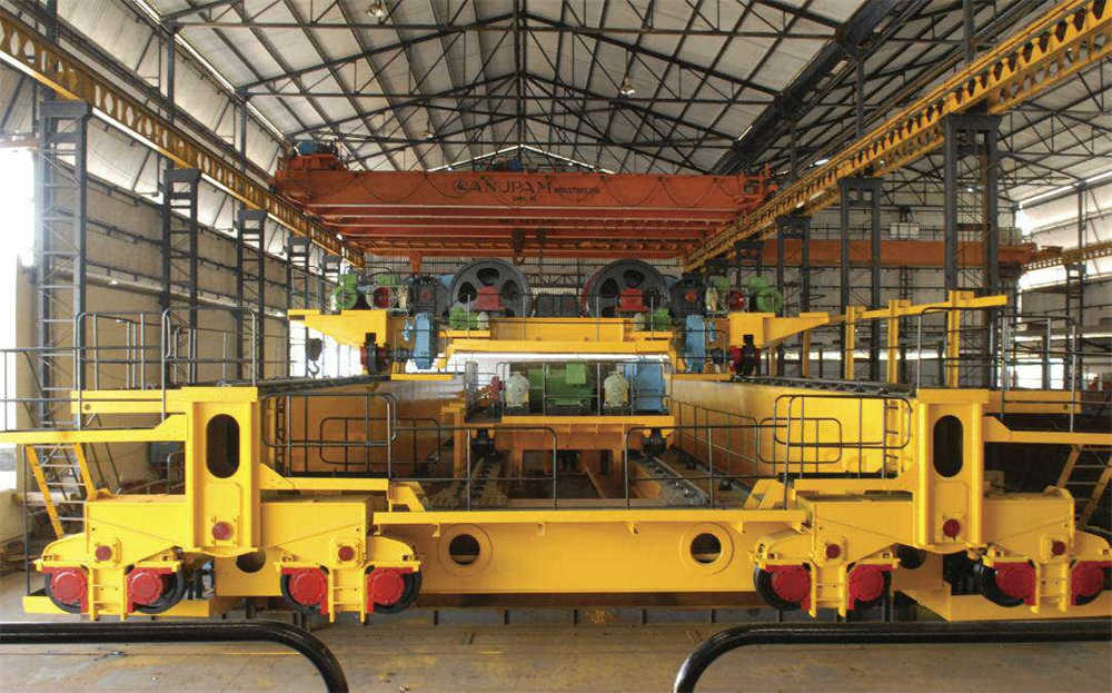
The structural and mechanical design of this type of extra-large heavy-duty ladle crane adopts technologies such as fatigue calculation, finite element analysis and resonance elimination. It has fewer spare parts and lower maintenance complexity.
Contact our crane specialists
Send us a message and we will get back to you as soon as possible.