In the heavy industrial equipment sector, gantry cranes, as core equipment in material handling systems, have a direct impact on production safety and operational efficiency. General-purpose gantry cranes with a rated lifting capacity between 100 and 20 tons must strictly adhere to the principles of steel structure mechanics and mechatronics specifications, ensuring structural strength and operational stability through standardized design. Modern manufacturing processes require a modular design concept to ensure precise assembly of key components such as the main beam and outriggers, while also meeting dynamic load distribution requirements under varying operating conditions. Technical performance indicators cover core elements such as lifting height, span parameters, and wind resistance rating, and must be coordinated with the electrical control system to establish a multi-layered safety protection system.
Gantry cranes, as heavy equipment widely used in industry, warehousing, and ports, must strictly adhere to a series of national and industry-developed standards during their design and manufacturing process to ensure high safety and reliability throughout their lifecycle. This standard system covers not only the setting of equipment performance parameters, structural strength calculations, and material selection and use, but also encompasses manufacturing processes, quality inspection, installation and commissioning, and maintenance.
GB/T 14405-2011, “General Gantry Cranes,” serves as a foundational national standard, defining the equipment’s basic parameters, technical requirements, and test methods. This standard provides comprehensive and detailed technical requirements for all aspects of gantry crane design, manufacturing, installation, commissioning, inspection, and maintenance, providing strong assurance for the equipment’s normal operation and safety. Industry standards such as JB/T 1306-2008, “Electric Single-Girder Cranes,” provide supplementary requirements for specific components. These standards further refine the requirements for gantry crane design, manufacturing, installation, commissioning, inspection, and maintenance, providing strong support for the healthy development of the industry. The international standard ISO 4306-1:2007, “Crane Terminology,” is a valuable reference for international projects. It standardizes crane-related terminology and definitions, facilitating international communication and cooperation.
During the design phase, designers must thoroughly implement the concept of “safety redundancy” to ensure the equipment possesses sufficient strength and stability to withstand a variety of expected and unexpected loads. As the primary load-bearing structure of gantry cranes, steel structures must be designed in strict compliance with GB 50017-2017, the “Standard for Steel Structure Design.” This standard details requirements for material selection, strength verification, connection design, and anti-corrosion treatment, ensuring sufficient strength and durability during use.
During the manufacturing process, companies must strictly adhere to the relevant requirements of TSG Q7002-2019, the “Type Test Rules for Hoisting Machinery.” This standard comprehensively regulates the manufacturing process of hoisting machinery, including key aspects such as raw material procurement and acceptance, welding process development and implementation, and dimensional accuracy control. In particular, the inspection and assessment of critical welds must meet the standards for Class 1 welds in GB 50661-2011, the “Code for Welding of Steel Structures,” to ensure reliable weld quality and the absence of potential hazards.
In terms of material selection, Q345B and higher low-alloy steel is preferred for primary load-bearing structural components. This material has a high yield strength and excellent weldability, meeting the load-bearing requirements under various demanding operating conditions. Transmission components such as gearboxes and pulleys are constructed from ZG310-570 steel castings to ensure transmission stability and reliability. Furthermore, the steel plate pretreatment process requires shot blasting to remove scale, rust, and other impurities from the surface, improving the coating’s adhesion and corrosion resistance. The anti-corrosion coating system complies with the HG/T 3656-2008 “Paint for Steel Structure Bridges” standard, ensuring excellent weather and corrosion resistance, providing a strong guarantee for the long-term stable operation of the equipment.
Table: Standard table for selection of main materials for gantry cranes
| Component Category | Material standards | Material grade/type | Performance requirements | Pretreatment process | Related test standards | Typical application areas |
| Main load-bearing structural parts | GB/T 1591-2018 | Q345B and above low alloy steel | High yield strength, good welding performance | Shot blasting and rust removal Sa2.5 level | GB/T 2975-2018 Sampling of Steel Products | Main beam, outriggers, end beams |
| Transmission components | GB/T 11352-2009 | ZG310-570 cast steel | High tensile strength and wear resistance | Heat treatment normalizing | GB/T 9443-2019 Flaw Detection of Steel Castings | Gearbox, pulley block |
| Connecting fasteners | GB/T 3098.1-2010 | High-strength steel grade 8.8 and above | Tensile strength ≥800MPa | Galvanized/Dacromet treatment | GB/T 228.1-2021 Metal Tensile Test | Bolts, pins |
| Anti-corrosion coating | HG/T 3656-2008 | Epoxy zinc-rich primer + polyurethane | Salt spray resistance ≥1000h, adhesion ≥5MPa | Sandblasting | GB/T 5210-2006 Coating Adhesion | Steel structure exterior |
| Wire rope | GB/T 20118-2017 | 6×36WS+IWR structure | Minimum breaking force ≥1770MPa | Grease impregnation | GB/T 8358-2014 Breaking strength of wire rope | Lifting mechanism, traction system |
| Electrical components | GB 14048.1-2012 | IP55 protection level | Heat and humidity resistance, vibration resistance | Leakage test | GB/T 2423.10-2019 Vibration test | Control cabinet, motor |
Table: Key process execution standards for gantry cranes
| Process | Implementation standards | Process parameter requirements | Quality inspection methods | Acceptance indicators | Equipment Requirements | Personnel qualifications |
| Welding process | GB 50661-2011 | Preheating temperature ≥120℃ (Q345B) | Ultrasonic testing (UT) | First-level weld compliance rate 100% | Digital welding machine | Certified welder (AWS/EN) |
| Machining | JB/T 5000.10-2007 | Dimensional tolerance IT7 | Three-coordinate measuring machine | Geometric tolerance ≤ 0.1 mm/m | CNC machining center | Senior technician |
| Assembly and debugging | TSG Q7002-2019 | Main beam camber (0.9-1.4) S/1000 | Total station measurement | Static stiffness ≤ S/800 | Laser Plummet | Lifting machinery assembler |
| Coating process | ISO 12944-5:2018 | Dry film thickness ≥200μm | Magnetic thickness gauge | Adhesion ≥5MPa | Airless spray equipment | NACE Certified Paint Applicator |
| Load test | GB/T 14405-2011 | Dynamic load 1.1Gn/static load 1.25Gn | Strain gauge testing system | No permanent deformation of the structure | 500t hydraulic loading system | Special equipment inspector |
| Electrical safety testing | GB 5226.2-2008 | Insulation resistance ≥ 1MΩ (500V megohmmeter) | Hipot tester | Leakage current ≤10mA | Safety comprehensive tester | Registered Electrical Engineer |
In crane design and configuration, a 10% overload protection threshold must be implemented for cranes with a rated lifting capacity between 20 and 100 tons. This effectively prevents equipment damage, safety incidents, and reduced service life due to overloading. For standard spans, a range of 18 to 35 meters is specified. For non-standard spans, detailed girder static and dynamic stiffness calculations are required to ensure that structural strength and stability meet requirements. Furthermore, for cranes with twin girder structures, the vertical static deflection should not exceed 1/800 of the span; for cranes with single girder structures, the vertical static deflection should not exceed 1/700 of the span. These requirements are intended to ensure stability and safety during lifting operations.
The crane’s hoisting speed must be controlled within the range of 5-15 m/min, and the trolley’s travel speed should be between 20 and 45 m/min. To ensure efficient and stable operation, the variable frequency speed control system must have four-quadrant operation capability, meaning it can operate smoothly under various operating conditions, including forward, reverse, and regenerative braking. Braking deceleration should be reasonably controlled between 0.2 and 0.5 m/s² to avoid equipment impact and damage caused by over-aggressive braking. Furthermore, the design, manufacture, and installation of the control system must strictly comply with the requirements of GB 5226.2-2008, “Safety of Machinery – Mechanical Electrical Equipment,” to ensure overall equipment safety, reliability, and stability.
The crane utilizes a 380V/50Hz three-phase AC power supply with a voltage fluctuation tolerance of ±10% to ensure stable operation under various operating conditions. As a core component, the motor must meet at least IP54 protection and Class F insulation to ensure optimal performance and safe operation in harsh environments. Busbar power supply requires a phase detection device to ensure stable and safe power supply. Cable reel power supply requires a tension adjustment mechanism to prevent damage caused by cable slack or excessive stretching.
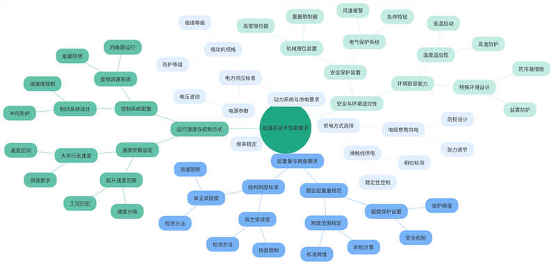
Key safety devices such as a load limiter, height limiter, and travel limit switch must be installed. A wind speed alarm should trigger an early warning when wind speeds reach 20 m/s, alerting the operator to safety risks and allowing them to take appropriate action. Emergency stop buttons should be located at both ends of the operator’s cab and platform, ensuring a response time of no more than 0.5 seconds to quickly stop the equipment in an emergency.
The crane must operate normally within an ambient temperature range of -25°C to +50°C, ensuring stable operation in various seasons and climates. For high-humidity environments (relative humidity ≥ 95%), anti-condensation heating devices must be installed to prevent damage or performance degradation caused by condensation. For use in coastal areas, the equipment must also pass the C4 salt spray test in accordance with GB/T 15957-1995 “Classification of Atmospheric Corrosivity” to verify its corrosion resistance and reliability in marine climates.
The main girder of the box-type double-girder structure adopts an off-track design, which improves structural strength and stability. The web spacing is no less than 1.2m, which increases structural rigidity and load-bearing capacity. The legs adopt an “eight” or “O” shape, which increases structural strength and stability, while also improving wind resistance and anti-slip capabilities. The connection between the legs and the main girder is a critical component of the entire structure and requires finite element analysis to ensure the strength and stability of the connection.
The cantilever length does not exceed 20% of the span to ensure structural stability and safety. The droop at the cantilever end is controlled within L/500 to ensure structural accuracy and stability. The hoist rotation mechanism requires a mechanical anti-rotation device to prevent unexpected rotation during operation. The wire rope uses a 6×37+FC structure, which increases the strength and wear resistance of the wire rope and also provides a safety factor of no less than 5, thus ensuring the safety and reliability of the structure.
The PLC control system should include self-diagnostic fault detection to facilitate repair and maintenance. Important signals should be backed up using hardwired circuits to ensure signal stability and reliability. Door limits and the lifting mechanism should be electrically interlocked to ensure structural safety and reliability. The end buffers should automatically cut off the operating power supply when triggered, ensuring structural safety and stability. The lighting system should maintain an illumination of no less than 50 lux to ensure operator safety and comfort.
In the crane’s design and configuration, polyurethane buffers must be installed at both ends of the traveling mechanism. These have excellent energy absorption properties, ensuring they can absorb at least 50 kJ of energy in an emergency, effectively reducing the risk of damage to equipment and personnel from impact forces. The design and material selection of the operator’s cab strictly adhere to the national standard GB/T 20303.1-2016 “Crane Operator’s Cab,” ensuring the operator has a good field of view and a comfortable working environment during operation. The panoramic glass must have a light transmittance of ≥70%, ensuring ample daylight and providing a clear field of view when necessary. The walkway railing height is set to a minimum of 1.05 meters, with the spacing between intermediate crossbars strictly controlled to ≤0.5 meters. This design is both ergonomically sound and provides adequate protection from the impact of accidental falling objects.
Annual inspection of equipment is critical to ensuring its safe and efficient operation. Testing the residual strength of the wire rope and testing the braking torque of the brake are essential. Every 500 operating hours, the reducer’s lubricating oil must be thoroughly inspected to ensure the lubrication system is always in good condition. Critical structural components must undergo magnetic particle inspection every three years. Any cracks exceeding 10% of the plate thickness must be replaced immediately to eliminate any safety hazards.
Operators must hold a Class Q2 Special Equipment Operator Certificate, the basic qualification for this type of operation. Operators must also receive at least eight hours of annual refresher training to maintain familiarity with the latest safety standards and operating procedures. Training emphasizes the study and application of the relevant practical provisions in GB 6067.1-2010, “Safety Regulations for Lifting Machinery.” Commanders, in addition to accurately interpreting signals, must also be proficient in the hand signals specified in GB 5082-85, “Command Signals for Lifting and Hoisting,” to ensure accurate, timely, and safe command and coordination throughout the entire lifting process.
Table: Operator Qualification Requirements
| Qualification/Requirement Type | Specific requirements | Relevant standards/specifications | Training/testing frequency | Key indicators/limitations |
| Special equipment operation certificate | Must hold a Q2 certificate | Measures for the Supervision and Management of Special Equipment Operators | Valid within the validity period after initial certification | No work without a license |
| Annual retraining | At least 8 hours of study per year | GB 6067.1-2010 Safety Regulations for Lifting Machinery | Once a year | Contains practical terms learning |
| Command signal mastery | Master hand signals | GB 5082-85 “Lifting and Hoisting Command Signals” | Pre-job assessment | Signal misjudgment rate ≤1% |
| Driver’s cab operation qualifications | Comply with cab design standards | GB/T 20303.1-2016 Crane Operator’s Cab | Verification during equipment handover | Light transmittance ≥70% |
| Safety device awareness | Understand the functions of buffers and railings | _ | Pre-job training | Buffer energy absorption ≥50kJ |
Table: Safety protection and inspection requirements table
| Project Category | Configuration/Inspection Requirements | Technical Parameters | Implementation standards | Maintenance cycle | Failure threshold |
| Polyurethane buffer | Installation at both ends of the walking mechanism | Absorption capacity ≥ 50kJ | GB/T 3811-2008 | Annual inspection | Deformation>10% |
| Driver’s cab design | Panoramic glass configuration | Light transmittance ≥70% | GB/T 20303.1-2016 | Daily inspection | Crack length > 5cm |
| Walkway railing | Height ≥ 1.05 meters | Crossbar spacing ≤ 0.5m | GB 6067.1-2010 | Monthly inspection | Deformation > 3cm |
| Wire rope inspection | Residual strength detection | _ | GB/T 5972-2016 | 500 working hours | Wire breakage rate>10% |
| Brake testing | Braking torque detection | _ | JB/T 6406-2006 | 500 working hours | Torque deviation>15% |
| Structural parts flaw detection | Magnetic particle inspection | Crack depth ≤ 10% of plate thickness | NB/T 47013-2015 | 3 years | Crack depth>10% |
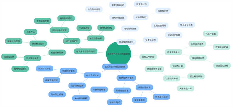
Given the often harsh weather conditions and complex mechanical equipment requirements of open-air operations, the following are some key technical requirements:
The steel structure surface treatment utilizes an epoxy zinc-rich primer + polyurethane topcoat system with a total dry film thickness ≥ 200μm. This coating system offers excellent corrosion protection and decorative properties, ensuring the long-term use of steel structures in open-air environments.
The protection level of electrical equipment is increased to IP65, and cable trays are equipped with UV-resistant sheaths. This ensures excellent waterproof and dustproof performance in open-air environments, extending the service life of the equipment.
The impact of permafrost depth must be considered in foundation design. In cold regions, the impact of permafrost depth on foundation design must be considered to ensure stable operation of the equipment in permafrost conditions.
To ensure the stability and safety of equipment in special environments, such as dock platforms, the following are some adaptive design requirements:
The allowable deviation of track installation must be controlled within ±2mm/m, and a track grounding device must be installed. This ensures equipment stability and operational accuracy. The hoisting mechanism is equipped with a dual braking system, with the second brake applying with a 0.5-1 second delay. This ensures that the equipment can be quickly stopped in an emergency, preventing accidents.
The hydraulic system must be equipped with an emergency hand pump. In the event of a hydraulic system failure, the emergency hand pump provides necessary backup to ensure normal operation of the equipment.
To ensure the normal operation and safety of the equipment in severe weather conditions such as high humidity and high winds, the following measures are recommended:
Install an automatic dehumidifier in the electrical cabinet and attach moisture-proof covers to the contactors. These measures effectively remove moisture from the cabinet and prevent damage to the equipment.
The wind-resistant anchoring device should be able to secure within 15 minutes, with an anchoring force of no less than 1/50 of the crane’s own weight. This ensures that the equipment can be stably fixed to the ground or platform in strong winds.
A real-time wind speed monitoring system should be installed, with data connected to the control center. This system monitors wind speed fluctuations in real time, providing operators with accurate wind speed information for timely response.
Contact our crane specialists
Send us a message and we will get back to you as soon as possible.