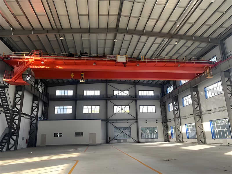
The QD5-16.5 A6 bridge crane is a medium-sized industrial crane with a rated lifting capacity of 5 tons, a span of 16.5 meters, and an A6 operating class. It is primarily used in industrial locations requiring high operating intensity. As the crane’s primary load-bearing structure, the design of the main girder and end beams is directly related to the safety, stability, and service life of the entire crane. This design utilizes a box-type double-girder structure, which offers high strength, rigidity, and stability, meeting the requirements of frequent lifting operations within the A6 operating class.
The box-type double-girder structure consists of two parallel main beams connected by end beams, forming a closed frame and a stable load-bearing system. The main beams primarily bear the concentrated load and distributed deadweight load from the trolley, while the end beams transfer the load to the crane’s trolley travel mechanism. Based on the operating environment and operational requirements, this design utilizes a separately driven trolley travel mechanism, eliminating the intermediate drive shaft. This effectively reduces structural weight and overall dimensions, while also preventing the impact of main beam deformation on trolley transmission performance.
The QD5-16.5 A6 crane’s main girder utilizes a box-section design, consisting of upper and lower decks welded to two vertical webs to form a closed, solid box-shaped plate girder structure. This closed section offers high bending and torsional rigidity, effectively resisting the complex stresses generated during crane operation. Considering the design’s high lifting capacity (5 tons) and moderate span (16.5 meters), transverse and longitudinal stiffeners are incorporated into the main girder to enhance the local stability of the webs and prevent buckling under concentrated loads.
The specific dimensions of the main girder require detailed calculations, but based on the technical parameters of a similar model (QD5T-16.5M), the following design parameters are recommended: span of 16.5 meters, trolley weight of approximately 2.12 tons, trolley wheelbase of 1.1 meters, and spreader weight of 0.1 tons. The main girder height is typically 1/14 to 1/18 of the span, and the width is 1/1.5 to 1/2.5 of the height. The web thickness should be no less than 6 mm, and the cover plate thickness should be no less than 8 mm. Specific values should be determined based on load calculations and regulatory requirements.
As the primary load-bearing component of a crane, the material selection is crucial. According to bridge crane design specifications, the main girder is typically constructed of Q235B or Q345B low-alloy, high-strength structural steel. Q345B steel is more suitable for this design due to its higher yield strength (≥345 MPa) and excellent weldability, particularly for the frequent use required within the A6 duty class.
The following factors should be considered when selecting materials:
Main beam design requires detailed strength and stiffness calculations to ensure the following basic requirements are met:
According to the calculation sheet for a similar model (QD5T-16.5M), the main beam calculations should consider the following load combinations:
The main beam strength calculation typically uses the allowable stress method to verify the maximum normal bending stress and shear stress in the mid-span and support sections. For the A6 working level, the basic allowable stress needs to take into account the working level coefficient c (about 0.75-0.85), and the material allowable stress [σ] is generally σs/(1.34-1.5).
The end beam is a crucial component of a bridge crane. It connects the two main beams to form the integral bridge structure and supports the entire crane on the track. The QD5-16.5A6’s end beam consists of a wheel-mounted end beam frame, primarily comprising the upper cover, web, and lower cover. The end beam adopts a segmented design, consisting of two sections connected by connecting plates and angle steel with high-strength bolts. This design facilitates transportation and installation.
Internal reinforcement ribs ensure the stability of the end beam frame under load. The end beam is rigidly connected to the main beam, ensuring overall structural stability. The midsection of the two end beams is detachably bolted, facilitating equipment maintenance and upgrades.
The end beam also adopts a box-shaped cross-section, forming a coordinated and unified load-bearing system with the main beam. The end beam height is typically the same as, or slightly less than, the height of the main beam ends to facilitate connection. Given that the end beam primarily bears bending and torque, its cross-sectional dimensions must be calculated based on the maximum wheel load and connection reaction.
The traditional method of connecting the main beam to the end beams can lead to the problem of running wheels not landing on the track at the same time, affecting the smooth operation of the crane. This design, drawing on a new connection method, considers using a combination pin assembly as the connecting element between the main beam and the end beams. This effectively avoids this problem while ensuring a safe and reliable connection.
The specific connection structure includes:
This new connection structure has the following advantages:
End beam design calculations primarily include the following:
Based on similar model parameters, the distance from the trolley’s running mechanism’s center of gravity to the nearest track centerline is a key calculation parameter, influencing wheel load distribution and drive power calculation.
The QD5-16.5A6 gantry crane utilizes a separate drive mechanism, with each end beam equipped with an independent drive unit. Compared to traditional centralized drive, separate drive offers the following significant advantages:
The gantry mechanism typically utilizes a “three-in-one” drive unit, integrating the motor, brake, and reducer. This design features a compact structure, high efficiency, and easy maintenance. Drive motor power calculations must consider factors such as the total crane weight, wheel load, operating speed, track friction, and wind resistance (outdoors), while allowing for a certain power reserve.
Based on the QD5T-16.5M specifications, the gantry operating speed is typically 20-30 m/min, and the motor power is approximately 2 × 2.2 kW. The brake must ensure sufficient braking torque so that the crane can stop smoothly within the specified distance and have wind and slip resistance (especially important when used outdoors).
The manufacturing process of a box-type main beam directly impacts the performance, safety, and reliability of a crane. The main process flow includes:
End beams are manufactured using the same box-type construction process, but special attention should be paid to the following:
The following quality indicators must be strictly controlled during the manufacturing process of the main beam and end beams:
After the main girder and end beam design is completed, a comprehensive design verification is required, including:
Based on calculation documents for similar models, the calculation contents for the QD5T-16.5M bridge crane include but are not limited to:
The QD5-16.5A6 bridge crane’s main and end beam designs feature the following innovations:
The design of the QD5-16.5A6 bridge crane’s main and end beams comprehensively considers structural strength, rigidity, stability, and operational performance requirements. The box-type double-beam structure and modular end beam design, combined with a novel connection method and separate drive systems, create a safe, reliable, and economical overall solution. Detailed calculations and analysis, combined with rigorous process control, ensure the crane’s long-term, reliable operation at the A6 operating level. Innovative design elements, such as the combined pin connection and three-in-one drive system, further enhance the product’s technical level and market competitiveness. This design meets the production needs of most small and medium-sized enterprises, from raw material handling to finished product loading and unloading, and has broad application prospects.
Contact our crane specialists
Send us a message and we will get back to you as soon as possible.