Home → News → Design scheme of 20t hook bridge crane
Design scheme of 20t hook bridge crane
I. Overview
Bridge cranes are essential material handling equipment in modern industrial production, widely used in workshop material handling, equipment installation, and maintenance. As a medium-sized lifting equipment, the 20t hook bridge crane plays a crucial role in industrial production. The rated lifting capacity of hook-type electric double-girder bridge cranes produced in my country ranges from 5 to 500t. Cranes over 10t are typically equipped with two main and auxiliary hoisting mechanisms, while cranes over 300t may have three.
Traditionally, the handling of large or heavy objects relied on levers and rollers, requiring significant manpower and time, resulting in low efficiency. However, the emergence of modern double-girder bridge cranes has greatly improved work efficiency and reduced labor intensity and workload. The 20t hook bridge crane designed in this paper utilizes a double-girder structure, making it easy to handle and lift cargo.
II. Design Parameters and Operating Conditions
2.1 Main Technical Parameters
Based on industry standards and actual requirements, the main design parameters of this 20t hook bridge crane are as follows:
Main Hoisting Mechanism:
Lifting Capacity: 20t
Lifting Height: 12m
Lifting Speed: 10m/min
Auxiliary Hoisting Mechanism (equipped on cranes 15t and above):
Lifting Capacity: 5t
Lifting Height: 14m
Lifting Speed: 20m/min
Traveling Mechanism:
Trolley Operating Speed: 45m/min
Carriage Operating Speed: 75m/min
Span: 22.5m (adjustable based on actual factory dimensions)
Working Class: A5 (suitable for medium-frequency applications)
2.2 Operating Environmental Conditions
This design is based on the following operating conditions:
Indoor environment, free of explosive gases and corrosive media
Ambient temperature: -20°C to +40°C
Relative humidity ≤ 85%
Altitude ≤ 1000m
Power Supply: Three-phase AC 380V, 50Hz
III. Overall Structural Design
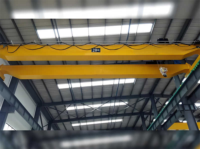
An electric double-girder overhead crane primarily consists of a bridge, trolley running mechanism, carriage running mechanism, and electrical equipment. The overall structure is shown in Figure 1.
3.1 Bridge Structure
The bridge, the main load-bearing structure of the crane, adopts a box-type design and consists of the following components:
Main Girder: A box-section structure consisting of an upper deck, web, lower deck, small ribs, large ribs, and longitudinal ties. The main girder design must consider strength and rigidity requirements to ensure that deflection under rated load does not exceed the allowable value.
End Girder (Cross Beam): Also adopting a box-section structure, it is welded to the main girder to form a complete bridge. Each end girder can be divided into two halves for ease of manufacturing and transportation.
Walkways and guardrails: Located on one or both sides of the bridge, they are used for installing and inspecting the running mechanism and electrical equipment.
Box-type bridges offer advantages such as simple manufacturing, high reliability, and easy maintenance, making them an ideal choice for medium-tonnage overhead cranes.
3.2 Gantry Mechanism
The gantry mechanism enables the entire crane to move laterally along the rails on both sides of the bridge, covering a wider operating range. This design utilizes a “three-in-one” drive system, combining the brake, reducer, and electric motor into one unit, resulting in a compact structure and easy maintenance.
The gantry mechanism primarily includes:
Drive motor
Reducer
Coupling (using gear couplings such as S1510KF and S2126)
Driver and driven wheel sets
Braking device
For 20t cranes, a four-wheel design (two active and two driven) is typically used. If wheel pressure is excessive, increasing the number of wheels can be considered to reduce the individual wheel pressure.
3.3 Trolley Design
The trolley is the core component of a bridge crane, comprising the hoisting mechanism and the operating mechanism. It can move longitudinally on the main girder of the bridge, expanding its operating range. The trolley structure is shown in Figure 2.
Trolley Mechanism:
Drive: Also uses a “three-in-one” drive system.
Operating Speed: 45 m/min.
Wheel Arrangement: Four-wheel structure, with calculated wheel pressures to ensure sufficient track load capacity.
Trolley design must consider compactness and lightweight while ensuring sufficient strength and rigidity. Modern design often utilizes 3D design software such as SolidWorks for modeling and optimization.
IV. Hoisting Mechanism Design
The hoisting mechanism is the most critical component of a crane, directly impacting its safety and reliability. The 20t hook bridge crane is equipped with two main and auxiliary hoisting mechanisms, enhancing operational flexibility.
4.1 Main Hoisting Mechanism
The main hoisting mechanism consists of the following key components:
Pulley Block: A double pulley block design prevents horizontal movement during lifting, ensuring a smooth lifting process and easy installation and replacement of the wire rope.
Wire Rope: Select the appropriate wire rope based on the lifting capacity, operating level, and safety factor requirements. The safety factor of the wire rope is generally no less than 5.
Hook Assembly: The 20t hook is forged from high-quality alloy steel and undergoes rigorous heat treatment and flaw detection. The hook assembly includes the hook, thrust bearing, hook crossbeam, and other components.
Drum: Used to wind the wire rope. The diameter, length, and wall thickness must be calculated to ensure sufficient rope capacity and strength.
Drive Unit: Includes the motor, reducer, brake, and coupling. The motor is connected to the reducer via a coupling and a brake wheel, and the reducer output shaft is connected to the drum.
Brake: A normally closed brake is used to ensure automatic braking in the event of a power outage, preventing heavy objects from falling.
4.2 Auxiliary Hoist
The auxiliary hoist’s design is similar to the main hoist, but with different parameters:
Lifting capacity: 5t
Lifting height: 14m (higher than the main hoist for auxiliary operations)
Lifting speed: 20m/min (faster than the main hoist)
The auxiliary hoist is primarily used for quickly transporting lighter objects and assisting the main hook in operations such as flipping.
V. Electrical Control System Design
The electrical equipment of a bridge crane primarily includes power drive, control, and protection systems.
5.1 Electric Traction Requirements
The electric traction system for each crane mechanism must meet the following requirements:
Hoisting mechanism: Capable of bearing the rated load, smooth starting, and good speed regulation performance.
Traveling mechanism: Capable of starting, braking, and reversing, with good trolley synchronization.
Provide necessary protection and interlocking functions.
5.2 Control Method
Use a linkage control console or remote control to control the starting, stopping, speed regulation, and reversing of each mechanism. Modern cranes are increasingly using variable frequency speed regulation technology to achieve smooth starting and precise control.
5.3 Safety Protection Devices
Overload protection: Limits the maximum lifting capacity.
Limit protection: Upper and lower lifting limits, operating limit positions.
Emergency stop: Cuts off power in an emergency.
Electrical interlock: Prevents misoperation.
Ⅵ. Calculation and Selection of Key Components
6.1 Wire Rope Selection and Calculation
When selecting a wire rope, consider the maximum working load, safety factor, and operating class. For a 20t main hoist:
Maximum working load: Approximately 24t after considering the dynamic load factor
Pulley ratio: 6 according to the design
Minimum breaking force of the wire rope: Calculated using a safety factor of 5
Final selection: 6×37+FC-20mm, nominal tensile strength 1870MPa
6.2 Drum Design Calculation
Calculation of main drum parameters:
Diameter: D ≥ 20d = 400mm (d is the wire rope diameter)
Length: Calculated based on the hoist height, pulley ratio, and number of winding layers
Wall thickness: Calculated using the formula for a compressed thin-walled cylinder
6.3 Motor Power Calculation
Main hoist motor power:
P = (Q·v) / (6120·η)
Where:
Q = 20t, v = 10m/min, η ≈ 0.85
Calculated P ≈ 38.5kW
Select a YZP series hoist-specific variable-frequency motor, 45kW
6.4 Brake Selection
Braking torque should meet the following requirements:
T ≥ K·(Q·D)/(2i)
Where:
K = 1.75 (safety factor), Q = 20t, D = 0.4m, i = reduction ratio
After calculation, select the YWZ5-400/E50 brake.
VII. Safety and Reliability Design
7.1 Structural Safety Factor
Main beam strength safety factor ≥ 1.5
Wire rope safety factor ≥ 5
Brake safety factor ≥ 1.75
7.2 Fault Protection Measures
Dual braking system
Automatic overload cutoff
Limit protection
Emergency stop button
7.3 Maintenance-friendly design
Easy access to all lubrication points
Modular design for easy component replacement
Rational placement of inspection platforms and walkways
VIII. Technological Innovation and Optimization
8.1 Structural Optimization
The main beam structure was optimized using finite element analysis to reduce deadweight, wheel load, and plant structure requirements while maintaining strength.
8.2 Energy-Saving Design
Variable frequency drive technology is used to reduce starting current.
Energy regenerative device and brake energy recovery.
High-efficiency reducer and motor.
8.3 Intelligent Upgrade
Reserved interfaces for:
Load monitoring system
Operation status monitoring
Remote fault diagnosis
IX. Economic and Technical Analysis
9.1 Manufacturing Cost Estimation
Metal Structure: Approximately 40%
Mechanical Components: Approximately 30%
Electrical System: Approximately 20%
Other: Approximately 10%
9.2 Operating Cost Analysis
Energy Consumption: Approximately 15 kW·h/working day
Maintenance: Annual maintenance costs approximately 5% of the equipment value
Service Life: Designed for 20 years
X. Conclusion
This 20t hook bridge crane design meets the various operating conditions required under A5 duty class and features a rational structure, safety, reliability, and easy maintenance. The double-girder box-type structure ensures sufficient strength and rigidity. The main and auxiliary hoisting mechanisms enhance operational flexibility, and the “three-in-one” drive system makes the operating mechanism more compact and efficient. The electrical control system incorporates safety protection and ease of operation, meeting the needs of modern industrial production. Through calculation and selection, all key components meet operational requirements, and the safety factor complies with relevant standards. This design can be used for material handling operations in machining centers, assembly workshops, warehouses, and other locations, significantly improving production efficiency and reducing labor intensity.
Contact our crane specialists
Send us a message and we will get back to you as soon as possible.