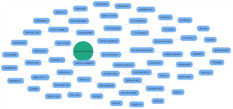
As an important equipment in modern industry, the design of the lifting mechanism of the double-beam box-type bridge crane is directly related to the efficiency and safety of the lifting operation. As the core component of the crane, the lifting mechanism not only bears the heavy task of lifting heavy objects, but also needs to ensure the smoothness and accuracy of the operation. This design specification aims to deeply explore the design details of the lifting mechanism of the double-beam box-type bridge crane, from the structural composition to the transmission scheme, to the design and verification of key components, and comprehensively analyze its working principle and performance characteristics. Through scientific design and calculation, it aims to improve the carrying capacity, operation stability and service life of the lifting mechanism, and provide a safer and more efficient lifting solution for industrial production.
Double-beam box-type bridge crane is a heavy-duty mechanical equipment, which is widely used in the industrial field. The structure of this crane is mainly composed of two parallel main beams, end beams, trolley running mechanism and lifting mechanism. Among them, the design of the main beam and end beam usually adopts a box section, which can improve the torsional strength and bearing capacity of the entire structure.
The working principle of the double-beam box-type bridge crane is to transport and position heavy objects through the lateral movement of the trolley on the main beam, the longitudinal movement of the trolley along the track, and the vertical lifting of the lifting mechanism. This type of crane has high working efficiency and stability and is widely used in various industrial fields.

The lifting mechanism is one of the core components of the double-beam box-type bridge crane, and its main function is to lift and lower heavy objects. By accurately controlling the speed and torque of the motor and the transmission ratio of the reducer, the lifting mechanism can achieve smooth and accurate lifting and lowering operations of heavy objects. In this process, the coordinated work of the pulley block, hook block, drum and other components is crucial. They not only determine the working efficiency of the lifting mechanism, but also directly affect the safety and reliability of the crane.
In the working process of the lifting mechanism, the design and selection of the pulley block has an important impact on the working efficiency and stability. The number and arrangement of the pulley block need to be designed according to actual needs to ensure that the heavy objects can move smoothly and accurately during the lifting process. The design and selection of the hook group is also very important. The structure and material of the hook group need to be able to withstand the weight and tension of the heavy object, and at the same time, ensure that there will be no problems such as slipping or falling off during use. The design and selection of the drum cannot be ignored. The drum needs to be able to withstand the tension of the heavy object, and at the same time, ensure that there will be no problems such as slipping or winding during the winding process.
When designing the lifting mechanism of a double-beam box-type bridge crane, the main goal is to ensure that the mechanism has sufficient load-bearing capacity, good stability and operational flexibility. At the same time, factors such as the maintenance convenience, energy consumption and noise level of the mechanism should also be considered. Design requirements include meeting specific lifting weights, lifting heights and working speeds, as well as complying with relevant safety regulations and standards.
On the premise of meeting basic functions, the design of the lifting mechanism should also focus on energy saving and environmental protection. The energy consumption and noise level of the lifting mechanism can be reduced by optimizing the speed and torque control of the motor and adopting measures such as efficient reducers. In addition, the maintenance convenience of the mechanism should also be considered to facilitate daily maintenance and maintenance.
The lifting mechanism of double-beam box-type bridge cranes is widely used in industrial fields such as heavy manufacturing, logistics warehousing, and port terminals. In heavy manufacturing, cranes are used to transport large parts, such as engines and frames; in logistics warehousing, they are used for the storage and handling of goods; in port terminals, they are mainly used for container loading and unloading operations. These application scenarios put forward different requirements on the performance of the lifting mechanism, such as fast response, heavy load capacity, long life, etc. Therefore, targeted design and selection are required according to different application scenarios and requirements.
The hoisting mechanism is one of the core components of the crane, and its structural design directly affects the performance and safety of the crane. Below we will introduce the various components of the hoisting mechanism and their design points in detail.
The hoisting mechanism is mainly composed of components such as motors, reducers, drums, pulley blocks, hook blocks and brakes. As a power source, the motor reduces the speed and increases the torque through the reducer to rotate the drum, thereby realizing the lifting and lowering of heavy objects. The drum is connected to the pulley block and hook block through a wire rope. The design of the pulley block can reduce the bending stress of the wire rope and increase its service life. The hook block is required to have sufficient strength and rigidity, and be easy to hook and unhook. The brake is used for emergency braking when necessary to ensure the safe operation of the crane.
The design of the pulley block mainly involves the number, diameter, material and matching relationship of the pulleys. Reasonable pulley block design can reduce the bending stress of the wire rope and increase its service life. The number and diameter of the pulleys mainly depend on the crane’s lifting capacity and working environment, and the material is required to have sufficient strength and wear resistance. The design of the hook group is required to have sufficient strength and rigidity, and to facilitate hooking and unhooking operations. The material of the hook group is generally made of high-quality steel, which is heat-treated and surface-treated to improve its durability and corrosion resistance.
The drum is one of the key components in the lifting mechanism, and its design must meet the requirements of load-bearing capacity and service life. The diameter, wall thickness, material, and shape and size of the drum groove must be accurately calculated. During the design process, the strength and stiffness requirements of the drum must also be considered to ensure that it will not undergo plastic deformation or cracking when subjected to the maximum working load. In order to meet these requirements, strength verification is usually required, and the drum is simulated and analyzed by methods such as finite element analysis to verify the rationality of its design and manufacturing.
In the lifting mechanism, the selection of motors and reducers is very important. The selection of motors needs to consider factors such as power, speed, torque, and working system. Power and speed depend on the lifting weight and working environment of the crane, while torque is required to meet the requirements of load capacity and working load. The selection of reducers needs to be based on factors such as the required transmission ratio, load capacity, noise level, and maintenance convenience. A reasonable combination of motors and reducers can ensure that the lifting mechanism has efficient and stable working performance. In addition, factors such as the installation size and weight of the motor and reducer need to be considered to ensure the stability and reliability of the entire crane.
Table: Motor parameter comparison table
| Motor Model | Power(kW) | Speed(rpm) | Torque(Nm) | Working system | Installation size (mm) | Weight(kg) |
| A-type motor | 10 | 1500 | 50 | S1 | 300×300 | 50 |
| B-type motor | 20 | 1200 | 100 | S3 | 350×350 | 70 |
| C-type motor | 30 | 900 | 150 | S2 | 400×400 | 90 |
| D-type motor | 40 | 750 | 200 | S1 | 450×450 | 120 |
Table: Reducer parameter comparison table
| Reducer model | Gear Ratio | Carrying capacity (kW) | Noise level (dB) | Maintenance convenience | Installation size (mm) | Weight (kg) |
| R type reducer | 10:1 | 20 | 65 | High | 320×320 | 60 |
| S type reducer | 15:1 | 30 | 70 | Medium | 370×370 | 80 |
| T type reducer | 20:1 | 40 | 75 | Low | 420×420 | 100 |
| U type reducer | 25:1 | 50 | 80 | High | 470×470 | 130 |
When designing and optimizing the hoisting mechanism of a crane, the selection of transmission scheme is crucial, and multiple factors need to be considered to ensure that the performance requirements, compactness, reliability and economy of the crane are met. First, it is necessary to deeply understand and analyze the specific structural characteristics and working conditions of the crane. For example, for large bridge cranes, which have a strong structure and large workload variations, gear transmission or worm transmission may be more suitable; while for small or precision lifting equipment, a more efficient and compact planetary gear transmission system may be required.
Next, a detailed technical and economic comparison is made for different types of transmission schemes, including but not limited to transmission efficiency, load capacity, maintenance cost, noise and vibration level, and space occupancy. For example, gear transmission has high transmission efficiency and load capacity, but may have problems such as high noise and high maintenance cost; while worm transmission can provide a large reduction ratio, but may have low efficiency under high load. Therefore, it is necessary to weigh various schemes in the design stage and conduct simulation tests in combination with actual application scenarios to determine the best transmission scheme.
In addition, it is also necessary to ensure that the selected transmission scheme complies with relevant national or industry regulations, such as regulations on transmission ratio, gear module, material selection, etc., according to design specifications and standard requirements. The final transmission scheme should take into account technological advancement, economic rationality and operational reliability, laying a solid foundation for subsequent design calculations and practical applications.
Power transmission path analysis is an important step in determining the interaction between the components in the lifting mechanism. By analyzing the power transmission relationship between the motor, reducer, drum, pulley block and hook group, the force conditions and movement laws of each component can be clarified, providing a basis for subsequent design and optimization. For example, the motor transmits power to the drum through the reducer, and the drum transmits power to the cargo through the pulley block and hook group to make it rise or fall. During the analysis process, it is necessary to consider the connection mode and transmission efficiency between the various components, as well as the force conditions of the cargo during the rise or fall process. By deeply analyzing the power transmission path, possible bottlenecks and problems can be found, and corresponding optimization solutions can be proposed.
Wire rope is a key component for transmitting tension in the lifting mechanism. Its selection needs to consider factors such as diameter, strength grade, structure type and use environment. The calculation process needs to determine the safety factor and allowable tension of the wire rope according to the load-bearing capacity and working conditions of the crane. For example, for large cranes, it is necessary to select a wire rope with a larger diameter and a higher strength grade to ensure that it can withstand a larger tension. At the same time, it is also necessary to consider the impact of the structural type of the wire rope and the use environment on its performance. In the calculation process, it is necessary to take into account the safety factor and allowable tension of the wire rope to ensure that it will not break or slip during use.
The calculation of motor power and torque is an important part of the design of the lifting mechanism. By considering factors such as the maximum working load, lifting speed, and transmission efficiency of the crane, the power and torque required by the motor can be calculated. This calculation result provides an important basis for the selection of the motor. For example, for large cranes, it is necessary to select a motor with larger power and torque to ensure that it can provide sufficient power and torque to drive the lifting mechanism. At the same time, it is also necessary to consider the impact of the transmission efficiency of the motor on its performance.
The strength verification of the output shaft of the reducer is one of the core links in the design of the lifting mechanism. As a key component of power transmission, the output shaft bears huge torque and radial force, so its strength and stability are directly related to the safe operation of the entire crane. When verifying the strength of the output shaft of the reducer, it is necessary to understand in detail the key parameters such as the maximum working load, rotation speed and strength limit of the material. The maximum working load refers to the maximum load that the crane may bear under normal operating conditions, including the rated lifting weight, dynamic load coefficient, static load coefficient, etc. The rotation speed refers to the rotation speed of the output shaft, which affects the load and lubrication of the bearing. The strength limit of the material refers to the allowable stress value of the material used in the output shaft. Depending on the material, the strength limit will also vary.
The stress distribution and deformation of the output shaft of the reducer can be simulated and analyzed by methods such as finite element analysis. During the simulation process, the three-dimensional model of the output shaft is imported into the finite element analysis software, and the corresponding loads and constraints are applied according to the actual working conditions. Through calculation and analysis, the stress distribution cloud map, deformation cloud map and displacement cloud map of the output shaft can be obtained. Through these results, it can be judged whether the output shaft meets the strength requirements. If the stress of the output shaft exceeds the strength limit of the material, or the deformation exceeds the allowable range, the structure of the output shaft needs to be optimized and improved.
In addition to the strength check of the output shaft of the reducer, the lifting mechanism design also needs to determine the main dimensions of the pulley and check the strength, check the motor overload and heat, and select the brake and coupling. The main dimensions of the pulley include diameter, width, shape and size of the rope groove, etc. The determination of these dimensions needs to consider factors such as the diameter, bending stress and service life of the wire rope. When determining the main dimensions of the pulley, it is necessary to ensure that the wire rope can slide smoothly in the pulley rope groove and have sufficient contact area to reduce stress concentration. It is also necessary to consider the strength and stiffness requirements of the pulley to ensure that plastic deformation or fracture will not occur when bearing the maximum working load.
Motor overload and heat verification are important links to ensure the safe operation of the motor. Overload refers to the load that the motor bears during operation exceeds its rated value, and heat refers to the heat generated by the motor during operation. In order to ensure the safe operation of the motor, overload and heat verification are required. This verification process needs to consider factors such as the rated power, working system and heat dissipation conditions of the motor. Rated power refers to the output power of the motor under normal operating conditions, and working system refers to the working system and working cycle of the motor. Heat dissipation conditions refer to the heat dissipation method and heat dissipation area of the motor. During the verification process, it is necessary to calculate the overload multiple and the maximum allowable overload time of the motor when it is subjected to the maximum working load, as well as the maximum allowable operating temperature and temperature rise limit.
The selection of brakes and couplings is also crucial for the safe operation of cranes. Brakes are used to brake the crane in an emergency to ensure its safe operation. When selecting brakes, factors such as its load capacity, braking performance and service life need to be considered. Load capacity refers to the maximum load that the brake can withstand, and braking performance refers to whether the brake can quickly and effectively stop the operation of the crane in an emergency. It is also necessary to consider the reliability and maintenance requirements of the brake to ensure that it can operate stably for a long time. Couplings are used to connect motors and reducers to transmit torque. When selecting couplings, factors such as its ability to transmit torque, the stiffness of elastic elements, and the requirements for centering need to be considered. The torque transmission capacity refers to the maximum torque value that the coupling can transmit, and the stiffness of the elastic element refers to the elastic deformation of the elastic element in the coupling when subjected to external force. It is also necessary to consider the installation and maintenance requirements of the coupling to ensure that it can meet the design requirements of the crane.
In the safe operation guarantee system of the crane, it is very important to configure a complete set of safety devices. These devices include not only limit switches, which are physical switches used to limit the travel of each moving part of the crane to ensure that it operates within a safe range and prevent mechanical damage or safety accidents caused by excessive movement; they also cover overload protection devices, which sense the load weight of the crane and immediately activate the protection mechanism once it exceeds the set threshold to avoid excessive pressure on the structural parts and power system due to overload, and effectively prevent the risk of equipment failure or even collapse caused by overload.
In addition, the emergency stop button is an indispensable safety emergency facility. Once an emergency occurs, the operator only needs to press the button to quickly cut off the power supply or activate the emergency brake system to ensure personnel safety and equipment protection; the anti-fall device is a safety guarantee measure designed for the lifting trolley and the hoisting device. It uses physical structure or hydraulic and pneumatic technology to ensure that the hoisted objects cannot fall off by themselves in unexpected situations, thereby preventing serious consequences caused by falling objects. These safety devices together constitute the line of defense for the safe operation of the crane, ensuring its reliability and stability under various working conditions.
Reliability analysis is a key link to ensure the safe and efficient operation of cranes. Through a comprehensive failure mode and effect analysis (FMEA) of each component of the crane, potential failures and their impact on equipment performance are predicted and evaluated. This analysis process helps the design team to accurately locate and prioritize key problem areas that may cause the whole machine to fail or reduce efficiency, and then propose targeted improvement design solutions, such as optimizing the structural design of components to reduce the failure rate, or selecting materials with higher durability and reliability to increase the life of components.
In order to implement reliability engineering at the actual operation level, it is also necessary to formulate a rigorous preventive maintenance plan, specify periodic inspection checklists and maintenance steps, including but not limited to regular wear detection of key components, replacement of severely worn parts, thorough cleaning of the whole machine, and necessary lubrication and maintenance. At the same time, it is crucial to strengthen the skills training of operators. Through regular professional knowledge and operating skills training courses, operators’ cognition and understanding of equipment performance can be improved, their daily operating behaviors can be standardized, and they can be able to timely discover and preliminarily deal with some common faults. In addition, training can also help enhance operators’ equipment maintenance awareness and form good equipment use and maintenance habits, thereby effectively improving the overall operation reliability and service life of the crane.
In order to ensure the long-term stable operation of the crane, a detailed maintenance plan needs to be formulated. This plan should include regular inspections, cleaning, lubrication, and replacement of wearing parts. Specifically, regular inspections can include daily basic inspections, weekly in-depth inspections, and monthly or quarterly comprehensive inspections. These inspections should cover the crane’s structural parts, electrical system, hydraulic system, lubrication system, brake system, and key components such as slings and slings. Basic inspections can promptly detect and solve potential problems to avoid equipment running with problems; in-depth inspections can provide a deeper understanding of the equipment’s condition and discover some problems that are not easily detected; comprehensive inspections are a comprehensive physical examination of the equipment to ensure that the overall operation of the equipment is in good condition.
In addition to regular inspections, cleaning is also an important part of maintenance. Cranes may accumulate a lot of dust, oil and other debris during operation, which may affect the normal operation of the equipment. Therefore, regular cleaning of the equipment can ensure the cleanliness and service life of the equipment. Lubrication is also an important part of maintenance. Regular lubrication can reduce equipment wear and extend the service life of the equipment. Finally, regular replacement of wearing parts is also an important part of maintenance. Wearing parts may wear or damage during long-term use. Regular replacement of wearing parts can ensure the normal operation of the equipment.
In addition, operators need to be trained to improve their maintenance awareness and skills. The training content can include the structure and working principle of the equipment, the maintenance and maintenance methods of the equipment, the operation and safety precautions of the equipment, etc. Through training, the skill level and safety awareness of operators can be improved, so that they can better use and maintain the equipment. At the same time, it can also enhance their sense of responsibility and mission, so that they pay more attention to the maintenance of the equipment.
Various faults may occur during the use of the crane. In order to eliminate these faults in time, it is necessary to master the fault diagnosis and troubleshooting methods. These methods include observing the fault phenomenon, analyzing the cause of the fault, taking corresponding measures to repair, and summarizing and improving after the fault. Specifically, when a fault phenomenon is found, the machine should be stopped and checked in time to observe the specific manifestations and characteristics of the fault phenomenon; then analyze the cause of the fault. When analyzing the cause of the fault, the following aspects should be taken: ask the operator in detail about the description and feelings of the fault phenomenon; observe the specific manifestations and characteristics of the fault phenomenon; check the working conditions of related components and systems; and finally determine the cause of the fault. After finding the cause of the fault, appropriate measures should be taken to repair it. The following points should be noted during the repair process: ensure the safety and reliability of the repair work; follow the correct repair procedures and methods; make necessary records and analysis during the repair process; and finally carry out necessary testing and verification. After troubleshooting, lessons learned should be summarized and improvements should be made in a timely manner: summarize the lessons learned during the analysis process; improve and perfect the weak links; improve the skills and safety awareness of operators; and finally strengthen the maintenance of equipment.
After in-depth and meticulous design and research on the lifting mechanism of double-beam box-type bridge crane, we have achieved remarkable results. The structural design of the lifting mechanism fully considers many factors such as mechanical properties, maintenance convenience and work efficiency. The overall structural layout is reasonable, and the matching accuracy and connection methods between various components have been carefully optimized to ensure that while meeting the needs of efficient operation of the crane, it can achieve long-term stable and reliable working conditions.
In the design and material selection of key components, we strictly follow relevant industry standards and international specifications, conduct detailed strength verification and fatigue life analysis, and are equipped with advanced safety protection devices, such as overload protection and limit protection, to maximize the safe operation of the crane under various working conditions.
During the design process, we actively introduced and applied a number of technological innovations and advanced technologies. For example, in the design of transmission scheme, we use advanced transmission technology and power calculation model to significantly improve the transmission efficiency and power utilization of the lifting mechanism; by optimizing the arrangement of the pulley group and the structural layout of the hook group, the bending stress of the wire rope during operation is effectively reduced, thereby extending the service life of the wire rope and reducing maintenance costs.
In the selection of brakes and couplings, we focus on improving the load capacity and braking performance. The brake is made of high-performance materials, has a sensitive and reliable braking effect, and can quickly and accurately stop the fall of heavy objects under various working conditions; the coupling is made of high-strength, low-creep materials to ensure that it can maintain stable torque transmission performance under long-term high-load operation. The introduction of these technical innovations and highlights has significantly improved the performance of the lifting mechanism.
Although we have achieved certain results in the design of the lifting mechanism, there are still some shortcomings. For example, in the optimization of transmission schemes, we can further explore new transmission technologies, such as electric hydraulic transmission and permanent magnet synchronous motor drive, to achieve a more efficient and lower energy consumption transmission effect; in the lightweight design of key components, we can reduce the weight of components and improve the energy efficiency of the whole machine by improving material properties and optimizing structural dimensions; in the intelligentization of safety devices, we can introduce advanced equipment and technologies such as Internet of Things technology and intelligent sensors to realize remote monitoring, fault diagnosis and other functions, and further improve the safety and reliability of cranes.
With the continuous development and technological progress in the industrial field, the application prospects of the lifting mechanism of double-beam box-type bridge cranes will be broader. In the field of heavy manufacturing, the efficient and reliable performance of the lifting mechanism will help enterprises improve production efficiency and reduce production costs; in the field of logistics and warehousing, the intelligent and automated technology of the lifting mechanism will promote the modernization and refinement of warehousing management; in the field of ports and terminals, the ultra-high strength and durability of the lifting mechanism will meet the needs of large-scale cargo loading and unloading. In the future, with the advancement of intelligent manufacturing and Industry 4.0, lifting mechanisms will further realize digitalization, networking, and intelligent development, providing important support for the progress of the global industrial field.
Contact our crane specialists
Send us a message and we will get back to you as soon as possible.