During the installation of large-scale industrial equipment, double-girder overhead cranes, as critical material handling equipment, have a direct impact on production safety and efficiency. Modern industry places higher demands on crane installation, requiring strict adherence to standardized operating procedures and acceptance specifications. From track laying accuracy to bridge assembly, from electrical system commissioning to safety device testing, every step requires thorough oversight by professional technicians. The installation process involves high-risk procedures such as overhead work and hoisting, necessitating the establishment of a comprehensive safety management system. During the acceptance phase, equipment performance is thoroughly tested according to national standards to ensure that all technical parameters meet the standards.
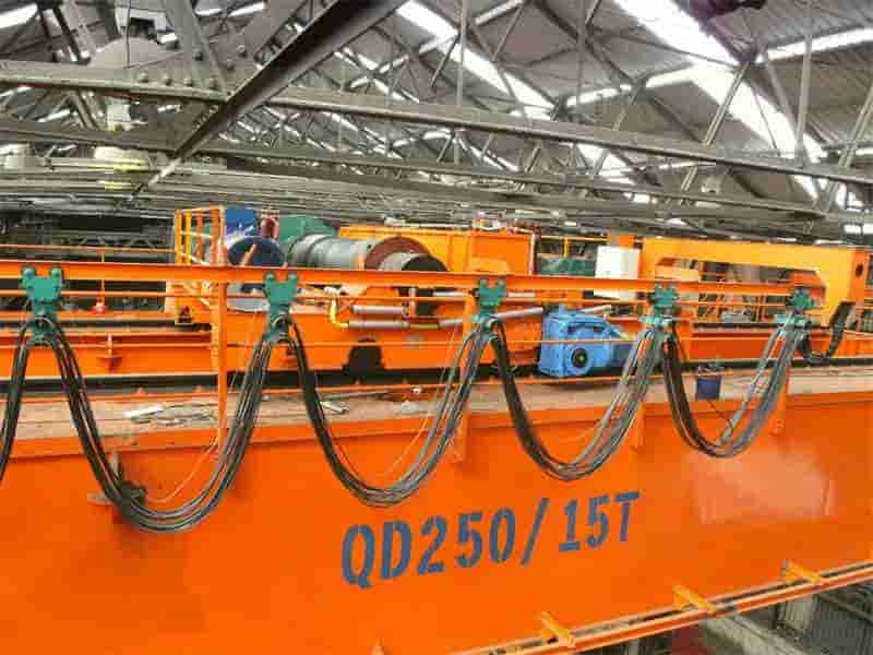
This project involves the installation of a major lifting equipment project, specifically a double-girder overhead crane with a rated lifting capacity of 20/5t. The crane has a span of 22.5 meters and can handle a variety of complex lifting requirements. Its service level is A5, indicating that under normal operating conditions, the crane can withstand heavy workloads and maintain efficient and stable operation. When developing the installation plan, we strictly adhered to relevant national standards and specifications, including GB/T 14405-2011 “General-purpose Bridge Cranes” and GB 6067.1-2010 “Safety Regulations for Lifting Machinery.” These specifications detail requirements for crane design, manufacturing, installation, operation, and maintenance, ensuring crane safety and reliability. We also fully referenced the technical documentation provided by the equipment manufacturer, which includes detailed equipment parameters, structural features, operating requirements, and maintenance information, providing strong technical support for our installation work.
The installation area is located in a heavy machinery manufacturing workshop, where the floor load-bearing capacity must meet a 12t/m² requirement. To ensure a smooth installation, we fully considered the floor load-bearing capacity requirements when developing the plan and implemented appropriate measures, such as strengthening the floor support structure and properly distributing the equipment weight, to ensure safety and stability throughout the installation process.
Table: Basic information table of lifting equipment installation project
| Parameter name | Parameter Value/Description | Technical standard basis | Installation environment requirements | Manufacturer’s Reference Documents |
| Device Type | Double-girder bridge crane | GB/T 14405-2011 | Heavy machinery manufacturing workshop | Equipment Technical Manual |
| Rated lifting capacity | 20/5t | GB 6067.1-2010 | Ground load ≥12t/m² | Structural drawings |
| Span | 22.5m | _ | _ | Load test report |
| Work Level | A5 | Manufacturer’s operating manual | _ | Maintenance Guide |
| Safety protection level | Complies with GB 6067.1-2010 | Electrical Safety Regulations | Dust and moisture-proof environment | Safety certification |
Table: Lifting Equipment Installation Engineering Specifications and Resources
| Specification Category | Specific standards/documents | Scope of application | Key requirements | Relevant responsible parties |
| Design Specifications | GB/T 14405-2011 | Structural strength and stability | Material yield strength ≥235MPa | Design Institute |
| Safety Regulations | GB 6067.1-2010 | Installation and operation safety | Mandatory installation of limit devices | Safety supervision department |
| Electrical standards | GB 5226.2-2008 | Control system and wiring | Insulation resistance ≥ 1MΩ | Electrical construction unit |
| Ground load-bearing acceptance | Workshop geological survey report | Foundation bearing capacity verification | Settlement ≤5mm | Civil engineering contractor |
| Manufacturer’s technical documentation | Hoisting balance calculation | Mechanical analysis of the installation process | Deflection ≤ span/800 | Equipment Supplier |
During the crane installation project, the design drawings were thoroughly reviewed to ensure a thorough understanding and mastery of all technical requirements, installation standards, and safety regulations. Key technical specifications for track installation were clearly defined, such as the strict control of the allowable deviation of the track centerline within ±5mm. This is crucial for ensuring stable and accurate crane operation. For the installation of the main beam, the camber must be strictly controlled within a reasonable range of (0.9/1000-1.4/1000)S to ensure sufficient strength and rigidity under load.
A specialized construction plan was developed and reviewed by experts, ultimately determining the use of a segmented hoisting process, with the main beam assembled and welded in two sections aerially. The construction plan was thoroughly discussed and rigorously validated to ensure its scientific and feasibility, fully accounting for various potential complexities encountered during the construction process. The segmented hoisting process, with the main beam assembled and welded in sections aerially, reduces the difficulty and risk of a single lift.
A total of eight personnel with crane machinery installation qualifications were deployed, including two certified welders and one electrician. These professionals possess extensive experience and relevant qualifications to ensure safety and quality during the construction process. Key equipment includes a 50t mobile crane, two laser theodolites, a hydraulic torque wrench (0-1000 N·m), and an ultrasonic flaw detector. These instruments will be used for lifting, measuring, bolt tightening, and testing. The credentials of the special operations personnel have been filed with the supervisor in advance to ensure their legality and validity.
All high-strength bolts (grade 10.9) undergo hardness retesting to ensure their mechanical properties meet regulatory requirements. The track pressure plates are made of Q345B steel, offering sufficient strength and rigidity. The wire rope is 6×37+FC-17.5mm in size and has a breaking strength of no less than 156kN, ensuring safety and reliability during the lifting process. All electrical components are certified by the CCC, demonstrating their quality and safety as recognized by authoritative organizations.
The track foundation concrete reaches C30 strength and has been cured for at least 28 days to ensure stability and safety. The position of the embedded parts was verified using a total station to an error of ≤2mm, ensuring their accuracy and reliability. Four temporary lifting points were set up on the roof of the workshop, each calculated to withstand a 15t load, ensuring safety and stability during the lifting process. Obstacles within a 10m installation radius were removed, and a warning zone was established to prevent unauthorized personnel from entering the site and creating safety hazards.
During the construction process, track installation accuracy is crucial to the operational stability and service life of the equipment. To ensure precise track installation, elastic pads are used to level the track, ensuring a tight fit between the track base and the foundation without any voids or gaps. To meet process requirements, the track gap at the joints is strictly controlled, not exceeding 2-4mm. When using fishplates as connecting components, the bolt preload must reach 90% of the rated value to ensure sufficient connection strength and stability. Track straightness is measured using specialized tools to ensure a deviation of no more than 3mm per 10m measurement section, and a cumulative deviation of no more than 15mm over the entire length. Furthermore, to meet safety requirements, the track grounding resistance must be tested to a value less than 4Ω.
As the crane’s primary structure, the bridge’s installation accuracy directly impacts its overall performance. Before hoisting the main beam, a stable temporary support frame must be set up to ensure construction safety. The mid-span pre-camber is adjusted to 28mm (calculated at 1.1/1000s) according to design requirements to compensate for deformation caused by deadweight and load. When connecting the end beams to the main beam, high-strength bolts are tightened in three stages, with the final torque deviation controlled within ±5% to ensure connection strength and stability. Laser measurement technology is used to precisely control the bridge’s diagonal deviation to within 8mm, ensuring the accuracy of the bridge’s geometry.
As a critical operating component of the crane, the trolley’s installation accuracy is equally critical. The tolerance band for trolley track spacing is set at ±3mm, and the height difference between two tracks within the same cross-section must not exceed 5mm. The vertical deflection of the wheels is limited to L/400 (L is the measured length), and the horizontal deflection is controlled within ±0.1% to ensure good wheel-rail contact and smooth operation. During the no-load test run, the trolley must not experience any jamming, and all wheels must maintain contact with the track.
During the electrical installation process, the insulation resistance of the power busbar must be greater than or equal to 1MΩ to meet safety requirements. The trolley travel mechanism utilizes advanced variable frequency control technology to improve operating efficiency and stability. The hoisting mechanism is equipped with dual brakes to ensure safe stopping in an emergency. The casings of all electrical equipment must be reliably grounded, with a grounding resistance not exceeding 0.1Ω, to reduce electrical noise and ensure operator safety. The lighting circuit is equipped with an independent leakage protection device to prevent safety accidents caused by leakage. The control system has undergone at least 10 fault-free simulated operation tests to ensure that all functions are normal, stable and reliable.
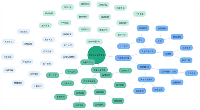
In terms of quality assurance, we have established a three-tiered inspection system to ensure that every process undergoes rigorous scrutiny. We implement a “three-inspection system” for process handovers: self-inspection, mutual inspection, and professional inspection. Key control points include UT testing of main beam welds (Level II qualified) and trolley travel noise ≤ 85dB(A). These measures ensure product quality and safety.
Quality records are managed using traceability numbers, ensuring that each quality record can be traced back to the corresponding product or process. Supervisors witness at least 30% of sampling to ensure product representativeness and authenticity. These measures provide strong assurance for our product quality.
All personnel involved in lifting operations must complete at least eight hours of specialized safety training, focusing on the “Ten Do Nots” in lifting operations, ensuring that every operator is familiar with and strictly adheres to them. Additionally, audible and visual alarms are installed in hazardous areas and key work points to warn of potential risks, and dedicated signalmen are deployed to provide on-site guidance and monitoring. A detailed JSA (Job Safety Analysis) is conducted at daily pre-shift meetings to ensure that every operator clearly understands the risks and countermeasures for the current operation, and is signed and confirmed by the relevant person in charge.
During lifting operations, the prohibition of standing within the operating radius is strictly enforced to ensure the safety of the work area. Furthermore, the wire rope safety factor must be ≥6 to ensure its load-bearing capacity and durability. For 50t cranes, the outriggers must be fully extended and a roadbed must be laid to increase stability during operation. Operations must be stopped immediately in wind speeds exceeding 8m/s to prevent accidents. Furthermore, all lifting equipment must undergo a 125% static load test before use to ensure safety and reliability. Safety Measures for Height Work
For work at heights above 2 meters, all workers must wear double-hook safety harnesses to ensure effective protection in the event of an accident. Mobile operating platforms must undergo rigorous load testing before use to ensure their load-bearing capacity and stability. Furthermore, tool bags feature fall-arrest designs, and loose parts are stored in locked tool boxes to prevent injuries from falling tools and parts during work. During cross-level work, rigid barriers are installed between levels to prevent accidents caused by falling objects.
For work in confined spaces, a strict “ventilation first, inspection second, work last” process is implemented. During operations, the oxygen content must be maintained between 19.5% and 23% to ensure respiratory safety for workers. Furthermore, the temporary power system is equipped with a secondary distribution box, and all cables are protected with flame-retardant conduit to reduce the risk of electrical fires.
In construction site management, we have implemented a number of measures to ensure a clean and safe environment. First, we have established standardized fencing in the component storage area, which not only effectively prevents dust and debris from drifting, but also ensures order on site. Second, waste materials are classified and stored in designated areas, and are regularly cleaned and disposed of to minimize environmental pollution. After each day’s construction, we have a dedicated team to clean up metal scraps to ensure a clean and tidy site. To deal with oil pollution, we use oil-absorbing cotton, a highly efficient and environmentally friendly material, to absorb and treat it, effectively preventing environmental damage. Furthermore, to ensure safe access to the construction site, the width of main passages is maintained at a minimum of 4 meters, ensuring that there are no obstructions.
We have also implemented a series of strict environmental protection measures. For example, during welding operations, to reduce the risk of smoke and dust to workers, we have deployed efficient mobile air purifiers to absorb the dust. Furthermore, for noisy operations, we strictly adhere to the designated rest periods for residents to minimize the impact on their lives. We entrust qualified professionals to safely handle waste grease and ensure its proper disposal. Furthermore, flushing wastewater undergoes a three-stage sedimentation treatment before discharge to minimize water pollution. Finally, to minimize the impact of nighttime lighting on surrounding residents, our lighting fixtures are equipped with sunshades to ensure a controlled illumination range.
The project manager serves as the overall commander of the emergency rescue leadership team, fully responsible for directing and coordinating all emergency response efforts. It comprises two specialized teams: a medical rescue team, comprised of qualified first aid personnel, including at least three certified first aid technicians, to ensure prompt and effective treatment of casualties and on-site first aid after an accident; and an emergency rescue and repair team, comprised of at least two mechanical engineers, responsible for troubleshooting mechanical equipment, repairing facilities, and maintaining order on site. A detailed emergency response procedure has been developed for three common accidents: crane overturning, electric shock, and falling from height, with a clear requirement for a response time of no more than 10 minutes.
Two automated external defibrillators (AEDs) have been prominently positioned on site for CPR in emergencies. Four hydraulic jacking systems are available for emergency support and repair in the event of a crane overturn or equipment failure. A professional drainage pump with a capacity of 200 m³/h has also been installed to address potential flooding and waterlogging. The emergency supplies list details essential protective and rescue equipment, including 20 tourniquets and 15 gas masks. A strict routine inspection system is implemented on the 15th of each month to verify the availability of all emergency supplies and ensure their proper functioning in critical situations.
To test and improve the practicality and feasibility of the emergency plan, multi-disciplinary practical drills are conducted quarterly. These drills cover a wide range of topics, including testing the reliability of the communication system, such as verifying the unobstructed operation of the three intercom backup channels; and practicing escape routes and evacuation procedures to ensure employees are familiar with and master these routes. The drills focus on assessing the stability and effectiveness of the communication system in emergency situations. After the drill, a detailed evaluation report is compiled, documenting key metrics, including the time required to transport the injured to the nearest tertiary hospital (approximately 3 km from the site). This allows for the subsequent analysis of lessons learned, continuous improvement of the emergency plan, and enhanced overall emergency response capabilities.
The steel structure undergoes rigorous inspection to ensure the absence of visible cracks, which is essential for ensuring overall structural integrity and safety. The anti-corrosion coating is applied strictly in accordance with requirements, with a dry film thickness of ≥120μm, to ensure adequate corrosion resistance and extend the service life of the steel structure. Bolt connections are a key connection method in steel structures. During acceptance, ensure that the final bolt tightening marks are intact. For high-strength bolts, the exposed threads should be maintained at 2-3 turns to facilitate regular inspection and tightening. Walkway railings and skirtings are critical safety features in steel structures. Walkway railings must be ≥1050mm high, and skirtings must be ≥70mm high. This design effectively ensures worker safety.
To ensure the proper operation of the electrical system, the motors undergo insulation resistance testing, with a value of ≥1MΩ, meeting safety standards. The emergency stop button’s response time is also rigorously tested. A response speed of ≤0.5s ensures rapid equipment shutdown in an emergency, effectively ensuring personnel safety. The controller’s zero-position interlock function is also verified for effectiveness. The sound pressure level of the audible and visual alarm system is ≥80dB, ensuring immediate attention. The cable drums are also carefully inspected to ensure that the cables are neatly wound and free of overlap to prevent damage or operational obstructions.
The crane’s safety performance was thoroughly inspected. The hoisting height limiter has a repeatability of ±20mm, ensuring accurate height control during lifting. The overload limiter has an error of ≤±5%, effectively preventing safety hazards caused by overloading. The trolley travel limiter has a trigger distance of ≥1.5m, and the buffer compression is ≥50mm. These data demonstrate stable performance and good cushioning during operation. The operator’s cab is equipped with a 2kg CO2 fire extinguisher to mitigate potential fires.
No-load tests are crucial for verifying crane performance. Each mechanism was tested 10 times in both the forward and reverse directions, demonstrating smooth operation without any unusual noises. Static load tests at 125% of the rated load showed the main girder’s downward deflection was ≤S/700 (measured value ≤32mm), demonstrating sufficient main girder rigidity and strength. Dynamic load tests, conducted at 1.1 times the rated load, involved repeated lifting and traveling maneuvers. Despite these rigorous tests, the crane’s structure showed no permanent deformation, fully demonstrating its reliability and stability.
Contact our crane specialists
Send us a message and we will get back to you as soon as possible.