As a core piece of equipment for modern industrial material handling, the design of a bridge crane’s trolley directly impacts the performance and reliability of the entire lifting system. This article provides a comprehensive technical analysis of the double-girder trolley for a 5-ton general-purpose bridge crane, delving into the engineering and technical implications of this critical piece of equipment, from structural design features and mechanical performance analysis to drive and hoisting mechanism configuration, safety measures, and innovative trends.
The double-girder trolley of a 5-ton general-purpose bridge crane is the most critical moving component in the entire crane system. Its design directly determines the crane’s operating efficiency, operational stability, and service life. As a medium-sized lifting device, the 5-ton double-girder trolley is widely used in the industrial sector, suitable for use in machinery manufacturing, assembly workshops, warehouse logistics, and various industrial and mining production processes. Compared to a single-girder design, the double-girder design offers better load distribution and greater stability, making it particularly suitable for industrial environments requiring medium lifting capacity and high operating frequency.
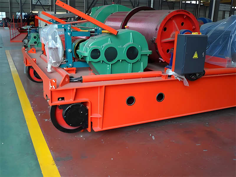
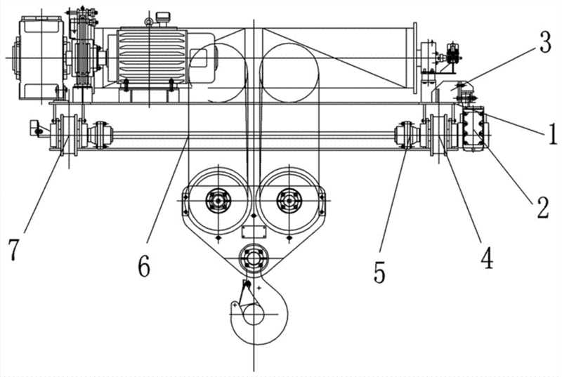
The basic components of a double-girder trolley include a steel frame, hoisting mechanism, operating mechanism, electrical control system, and safety protection devices. The steel frame serves as the load-bearing foundation for all other components and typically utilizes a combination of box beams and I-beams. This design ensures sufficient strength while optimizing weight. The hoisting mechanism is responsible for vertically lifting and lowering cargo and consists of a motor, reducer, brake, wire rope, pulley system, and hook assembly. The operating mechanism enables the trolley to move horizontally along the main beam track, precisely positioning the cargo within the span.
From a design parameter perspective, typical technical specifications for a 5-ton double-girder trolley include: a rated lifting capacity of 5 tons (main hook), a lifting height typically ranging from 12 to 18 meters (depending on actual requirements), a lifting speed of approximately 7.5 to 19 m/min (often designed with dual speed or variable frequency drive), and a trolley operating speed generally ranging from 20 to 40 m/min. The selection of these parameters requires a comprehensive balance between production efficiency, operational precision, and energy consumption. It is worth noting that the 5-ton double-girder trolley’s operating class is generally A5 (medium duty class), suitable for less frequent but more than occasional use. In terms of design philosophy, modern 5-ton double-girder trolleys adhere to the three principles of “safety, reliability, cost-effectiveness, and ease of maintenance.” Safety and reliability are reflected in structural strength redundancy, multiple braking safeguards, and a fault warning system. Cost-effectiveness is achieved through optimized powertrain configuration, reduced energy consumption, and the use of standardized components to lower manufacturing costs. Ease of maintenance is achieved through modular design, easily removable connections, and a centralized lubrication system. Furthermore, with the advancement of Industry 4.0, intelligent monitoring and remote control features are becoming standard features on high-end 5-ton double-girder trolleys, making equipment management more convenient and efficient.
Compared to traditional single-girder crane trolleys, 5-ton double-girder trolleys offer significant advantages: the double-girder structure provides greater rigidity, reducing deflection under load; the separate running gear ensures more even wheel pressure distribution, reducing rail wear; the ample overhead beam space allows for the installation of more complex lifting mechanisms and electrical equipment; and the symmetrical design provides enhanced torsional resistance, making the trolley suitable for lifting long materials. These advantages have made double-girder trolleys a dominant force in the lifting equipment market of 5 tons and above.
The structural design of a double-girder trolley is a key element in ensuring its load-bearing performance and service life. It requires comprehensive consideration of multiple requirements, including strength, rigidity, stability, and manufacturability. The double-girder trolley for a 5-ton general-purpose bridge crane utilizes a combined box girder and I-beam structure. This design cleverly combines the excellent bending resistance of the box girder with the superior shear resistance of the I-beam, achieving efficient material utilization. The ratio of the main girder cross-section height to span is typically controlled between 1:14 and 1:18. This ratio, proven through long-term engineering practice, ensures sufficient rigidity while minimizing material waste. Pre-setting the main girder camber is a key detail in structural design. Pre-fabricating the camber to a ratio of 0.9/1000 to 1.4/1000 of the span effectively compensates for deflection under load, ensuring the trolley maintains stable track contact even when fully loaded.
The end beam connection system is another critical component of the double-girder trolley structure. Its design quality directly impacts the overall operating smoothness and service life of the trolley. Modern 5-ton double-girder trolleys generally utilize a flange design with high-strength bolt connections. The connection surfaces are precision-machined to ensure a precise fit. This detachable connection ensures precise installation and facilitates subsequent maintenance and component replacement. The end beams often have integrated buffers to effectively absorb impact energy when the trolley reaches its extremes, minimizing structural damage. In actual designs, the end beams are typically designed with a greater strength margin than the main beams, as they bear not only vertical loads but also the horizontal inertial forces generated during trolley starting and braking.
The trolley frame, as the foundational platform for supporting and mounting the lifting and running mechanisms, is also crucial in its design. The trolley frame of a 5-ton double-girder trolley is typically a welded steel structure consisting of longitudinal beams, cross beams, and a steel platform. To reduce weight, a combination of box-section longitudinal beams and I-beam cross beams is often used to create a sturdy grid structure. The contact area between the trolley frame and the main beam features hardened steel wheel treads, slightly harder than the rails, to extend service life. The trolley frame also features dedicated mounting brackets for the motor and reducer, typically designed with adjustment shims to facilitate precise adjustment of the transmission component’s mounting position.
In terms of material selection, the main load-bearing components of 5-ton double-girder trolleys are generally made of Q235B or Q345B steel. Q235B, a common carbon structural steel, offers excellent plasticity and weldability at a relatively low price. Meanwhile, Q345B low-alloy steel boasts a higher yield strength (345 MPa vs. 235 MPa) and improved overall mechanical properties, making it particularly suitable for applications that are weight-sensitive or require high load-bearing capacity. High-strength alloy steel bolts, typically with a performance grade of 8.8 or 10.9, are used in critical joints to ensure reliable connections. With advances in materials technology, some high-end 5-ton double-girder trolleys are beginning to utilize H-section steel and special steel plates, further optimizing the ratio of structural weight to load-bearing capacity.
Structural optimization is a prominent feature of modern 5-ton double-girder trolley design. Finite element analysis allows designers to accurately simulate the stress distribution and deformation of the trolley under various operating conditions, enabling them to implement targeted structural reinforcement or weight reduction measures. Typical optimization measures include: adding stiffeners to stress-concentrated areas; creating weight-reducing holes in low-stress areas; optimizing cross-sectional shapes to increase the bending modulus; and carefully designing rib layouts to enhance local stability. These optimizations enable modern 5-ton double-girder trolleys to achieve a 10%-15% reduction in structural weight compared to traditional designs, while maintaining or even increasing their load-bearing capacity. This reduces energy consumption and track wheel pressure.
Table: Typical values of main structural parameters of 5-ton double-girder trolley
| Parameter name | Typical values | Design basis |
| Main beam section height | 1/14-1/18 span | Stiffness requirements |
| Main beam camber | 0.9/1000-1.4/1000 span | Compensate for load deflection |
| Material selection | Q235B or Q345B steel | Balance between strength and cost |
| End beam connection | High-strength bolt flange | Detachable precision connection |
| Number of wheels | 4 (2 for driving wheels) | Wheel pressure distribution |
The manufacturing process also has a decisive influence on the performance of the double-girder trolley. High-quality trolley structures require precise welding process control, including welding sequence control, preheating and post-heating measures, and non-destructive testing of welds. Major stress-bearing welds are usually required to meet Class 1 weld standards, and advanced welding methods such as submerged arc automatic welding are used to ensure quality. After processing is completed, key components also need to undergo stress relief heat treatment to reduce welding deformation and residual stress. The application of modern manufacturing technologies such as CNC cutting, robotic welding, and computer-aided testing has greatly improved the manufacturing precision and quality consistency of the 5-ton double-girder trolley, enabling the product to meet the increasingly stringent requirements of industrial applications.
The hoisting mechanism is the core functional component of a 5-ton double-girder overhead crane trolley. Its design directly determines the performance and reliability of the entire lifting system. The hoisting mechanism consists of five main components: a drive unit, a transmission system, a wire rope winding system, a hook mechanism, and safety devices. These components must work in perfect harmony to ensure smooth lifting and lowering of the load. In 5-ton general-purpose overhead crane designs, the hoisting mechanism typically utilizes a single-drum, single-motor drive. This arrangement is compact, easy to maintain, and fully meets the requirements of medium-intensity use (A5 duty class).
The drive unit is the power source for the hoisting mechanism. Modern 5-ton double-girder trolleys generally use three-phase asynchronous motors. Motor power typically ranges from 7.5 to 15 kW, depending on the lifting speed and duty class. Key parameters for motor selection include starting torque, overload capacity, and heat dissipation. In terms of electrical control, mid- to high-end configurations utilize variable frequency speed regulation technology to achieve stepless adjustment of the hoisting speed. This not only improves operational precision but also significantly reduces shock loads during starting and braking, extending the life of the mechanical structure. The motor is typically connected to the reducer via an elastic pin coupling or gear coupling. This arrangement allows for a certain degree of axis deviation and reduces the installation precision requirements.
The braking system ensures the safe operation of the hoisting mechanism. Dual braking systems have become the industry standard for 5-ton double-beam trolley hoists. The main brake typically utilizes an electro-hydraulic push rod brake or an electromagnetic brake, installed on the high-speed shaft (motor shaft or reducer input shaft). These brakes offer advantages such as adjustable braking torque, smooth braking, and reduced wear. Auxiliary brakes can be mechanical, load-controlled, or motor-operated, serving as a backup for the main brake or for use during main brake maintenance. Of particular note, the main brake’s braking torque is typically designed to be 1.75-2 times the rated torque, ensuring safe braking of the rated load even in the event of a sudden power outage.
The reduction gear converts the high speed and low torque of the motor into the low speed and high torque required by the drum. In 5-ton double-beam trolley designs, a three-stage gear reducer is the most common configuration. The first stage of the reducer typically utilizes helical gears, while the remaining two stages utilize involute cylindrical gears. This combination balances smooth transmission and manufacturing economy. The reducer’s design life is typically no less than 10 years, and the gear accuracy must meet a minimum of Grade 7 (GB/T10095). Heavy-duty roller bearings are used to withstand heavy radial loads. The reducer can be connected to the drum via direct flange connection or gear coupling. The former is more compact, while the latter facilitates installation and adjustment. The reducer is typically lubricated with oil immersion and is equipped with an oil level indicator and magnetic drain plug for easy maintenance.
The wire rope winding system, consisting of the drum, wire rope, pulley assembly, and hook assembly, is the key component in converting rotary motion into linear lifting motion. The drum of a 5-ton double-girder trolley is typically cast from QT450-10 ductile iron or welded from Q345B steel. Its surface features spiral grooves to guide the wire rope. The groove pitch is generally 1.1 times the wire rope diameter, and the groove bottom radius is slightly larger to reduce compressive stress. The wire rope is a 6×37+FC or 6×19+FC cross-lay wire rope with a nominal tensile strength of at least 1770 MPa and a safety factor of at least 5 per GB/T3811. The pulley system is typically designed as a two- or three-ratio system. The pulleys are made of ZG270-500 cast steel, and the grooves are surface-hardened for wear resistance.
As the component that directly carries the load, the safety of the hook is paramount. The 5-ton double-girder trolley is equipped with a standard forged hook made of DG20Mn or equivalent high-quality alloy steel, heat-treated, and magnetic particle inspected. The hook assembly is equipped with a thrust bearing, allowing the hook to rotate freely to prevent twisting of the wire rope. An anti-unhooking device prevents accidental drop of the load during lifting. Hook opening deformation inspection and scrapping standards strictly comply with GB/T10051 regulations to ensure safe use.
Table: Typical technical parameters of 5-ton double-beam trolley lifting mechanism
| Parameter name | Typical values | Technical basis |
| Rated lifting capacity | 5 tons | Design basis |
| Lifting height | 12-18m | Application Requirements |
| Lifting speed | 7.5-19m/min | Working Level |
| Motor power | 7.5-15kW | Load and speed |
| Wire rope diameter | 11-13mm | Safety factor ≥5 |
| Brake torque | 1.75-2 times rated | Safety standards |
Safety devices are an integral part of a hoisting mechanism. Modern 5-ton double-girder trolley hoists are equipped with multiple safety features: a limiter (weight or rotary encoder), an overload limiter (mechanical or electronic), undervoltage protection, and an emergency stop button. High-end configurations also incorporate features such as slack rope protection and phase mismatch protection. These devices are integrated with the control system via electrical interlocks, triggering an alarm and halting dangerous operations. It is particularly important to emphasize that the overload limiter is typically set at 105%-110% of the rated load, allowing for a reasonable operating margin while preventing dangerous overloading.
The lubrication system is equally crucial to the long-term, reliable operation of a hoisting mechanism. 5-ton double-girder trolley hoists utilize a combination of centralized and manual lubrication: the gears within the reducer are lubricated in an oil bath; bearings and open gears are typically lubricated with lithium-based grease, which is periodically manually added; and pulleys and hook bearings are equipped with grease nipples for easy lubrication. Advanced configurations utilize an automatic centralized lubrication system, which delivers lubricant to each lubrication point at a fixed time and in a fixed quantity, significantly reducing maintenance workload and the risk of human error. Correct lubrication management can reduce friction and wear and extend the life of components, and is the focus of daily crane maintenance.
The running mechanism of a double-girder trolley is the actuator system that moves along the crane’s main girder rails. It has a crucial impact on the crane’s positioning accuracy, operating smoothness, and service life. The running mechanism design of a double-girder trolley for a 5-ton general-purpose bridge crane requires comprehensive consideration of multiple factors, including the drive method, wheel-rail layout, transmission efficiency, and braking performance, to ensure safe, reliable, and cost-effective operation. Unlike the hoisting mechanism, the running mechanism primarily handles horizontal movement. Its design challenges lie in overcoming inertia during starting and braking, and ensuring good contact between the wheels and rails.
The drive layout is a key decision point in running mechanism design. Modern 5-ton double-girder trolleys generally adopt a unilateral drive arrangement, where the drive unit is installed on only one side of the trolley, connected to the wheels on the other side via a coupling or drive shaft. This arrangement is simple in structure, low in cost, and fully capable of meeting the 5-ton lifting capacity requirements. Specifically, the running mechanism of a 5-ton double-girder trolley typically features two driving wheels and two driven wheels. The driving wheels are rotated by the drive unit via a gear coupling or universal joint. For higher-level applications or more frequent use, a dual-drive arrangement can be considered. This arrangement involves installing a drive unit on each side, with electrical synchronization ensuring consistent speeds on both sides. This arrangement provides better traction but comes at a higher cost.
Drive unit selection has evolved from discrete components to integrated solutions. Traditional designs utilize separate motors, reducers, and brakes, connected via couplings. This arrangement facilitates individual component maintenance but occupies a large space. Modern 5-ton double-girder trolleys increasingly utilize a “three-in-one” drive unit, combining the brake, reducer, and motor into one unit. This offers significant advantages such as compactness, ease of installation, and reduced maintenance. This “three-in-one” drive unit typically utilizes a helical gear reducer or planetary gear reducer, achieving transmission efficiencies exceeding 96% and noise levels below 70 decibels, making it ideal for use in small and medium-sized bridge cranes. The motor is often a conical rotor brake motor or a three-phase asynchronous motor with an electromagnetic brake to ensure automatic braking in the event of a power outage.
The wheel and track system is the load-bearing foundation of the trolley, and its design directly impacts its operating resistance and service life. The wheels of a 5-ton double-girder trolley are typically made of ZG340-640 cast steel. Quenching treatment results in a tread hardness of HB300-380, slightly higher than the rail hardness to reduce wear. The wheel diameter is determined based on wheel pressure calculations and generally ranges from 250-400mm. A double-flange design is used to prevent derailment. The wheel bearings use spherical roller bearings, which automatically compensate for minor deformation of the trolley frame. The rails are typically P-type railway rails or QU-type crane rails, secured to the upper flange of the main beam by a pressure plate. The rail heads are precision-machined to ensure smooth rolling contact. The wheel and rail alignment requires strict control of track gauge tolerances (generally ±3mm) and levelness tolerances to minimize running resistance and abnormal wear.
The transmission system design is crucial to the efficiency and reliability of power transmission. The transmission mechanism of a 5-ton double-girder trolley primarily employs two types of transmission arrangements: parallel axis and coaxial. In a parallel-axis arrangement, the motor axis is parallel to the wheel axis, with speed reduction achieved through a horizontal reducer and open gear transmission. This arrangement facilitates maintenance but is less compact. A coaxial arrangement utilizes a vertical reducer, with the motor and wheel aligned coaxially. This is very compact but slightly more difficult to maintain. The gears in the transmission system must meet a minimum precision of Grade 7, and the tooth surfaces are hardened for wear resistance. Couplings are typically gear couplings or elastic pin couplings, allowing for some axis misalignment and facilitating installation and adjustment. High-end configurations utilize universal joints, which accommodate greater installation tolerances and deformation.
Operating speed control is a key factor affecting operational accuracy and structural load bearing. The standard operating speed of a 5-ton double-girder trolley is generally between 20 and 40 m/min, with the specific value depending on the application. Traditional control methods utilize a wound rotor motor with a series resistor for speed regulation. While cost-effective, this method also limits the speed range and consumes a lot of energy. Modern, advanced solutions utilize variable frequency speed regulation technology, enabling stepless and smooth adjustment from 0 to rated speed, allowing for precise control of both starting acceleration and braking deceleration. This not only improves positioning accuracy (up to ±5mm), but also significantly reduces dynamic loads during starting and braking, extending the service life of the steel structure and trolley components. Frequency conversion control also enables a “slow inching” function, facilitating precision assembly operations.
The braking system is the core guarantee for crane operational safety, and its reliability is directly related to equipment safety and the safety of personnel and property. Preventing the 5-ton double-girder trolley from sliding out of control, particularly in emergencies such as power outages, is a paramount concern in braking system design. To ensure absolute safety, the operating mechanism employs dual braking protection: the main brake, typically integrated into the “three-in-one” drive unit, utilizes advanced electromagnetic braking technology and serves as the primary braking device during daily operation, offering rapid response and smooth braking. An auxiliary braking system, capable of selecting either electromagnetic or mechanical brakes depending on actual operating conditions, provides a redundant safety feature, providing secondary protection in the event of main brake failure. This dual braking solution not only complies with national crane safety regulations but also effectively responds to various emergencies, providing a solid safety barrier for equipment operation.
Contact our crane specialists
Send us a message and we will get back to you as soon as possible.