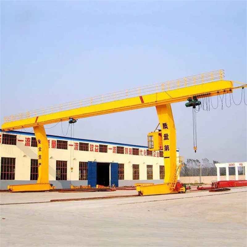
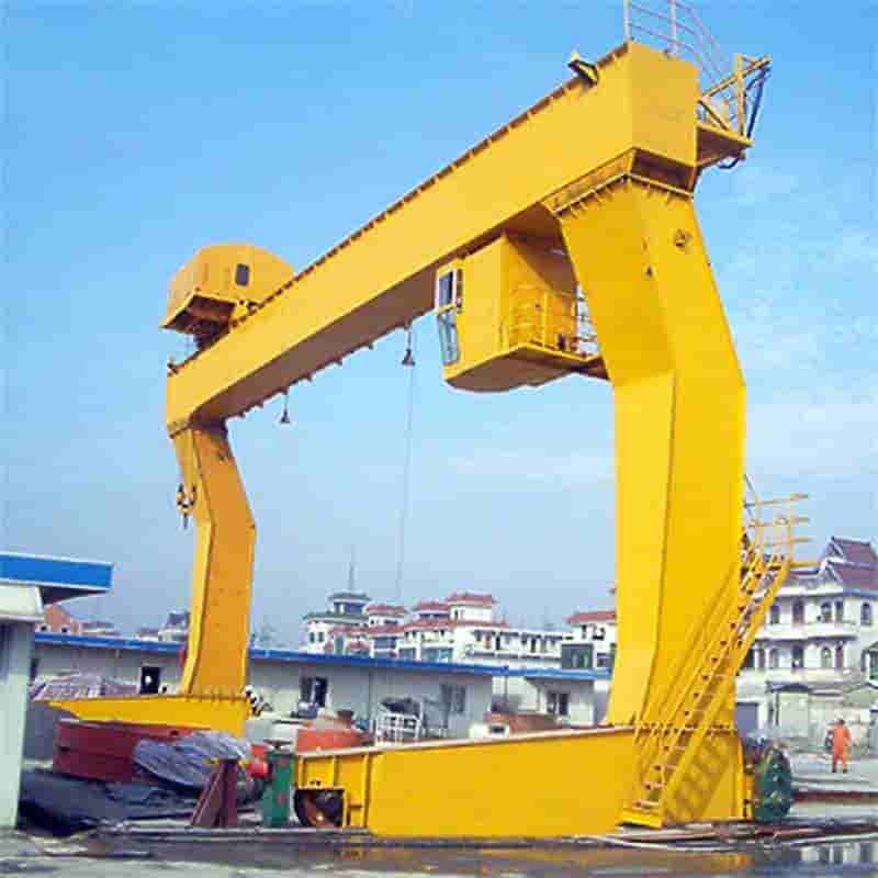
In industrial plants, logistics warehouses, and other sites, the L-type single girder gantry crane has become key equipment for material handling due to its compact structure and wide operating range. Its installation quality directly affects the operational stability and service life of the equipment, requiring strict adherence to standardized construction processes. This scheme forms a complete closed loop from technical preparation and on-site implementation to debugging and acceptance. Through core process controls such as precise positioning of the main girder and standardized wiring of the electrical system, it ensures that all crane performance indicators meet the requirements of the GB/T14406 standard. The installation process simultaneously implements a three-level safety protection system, providing dual assurance for high-risk aspects such as aerial work and large component lifting.
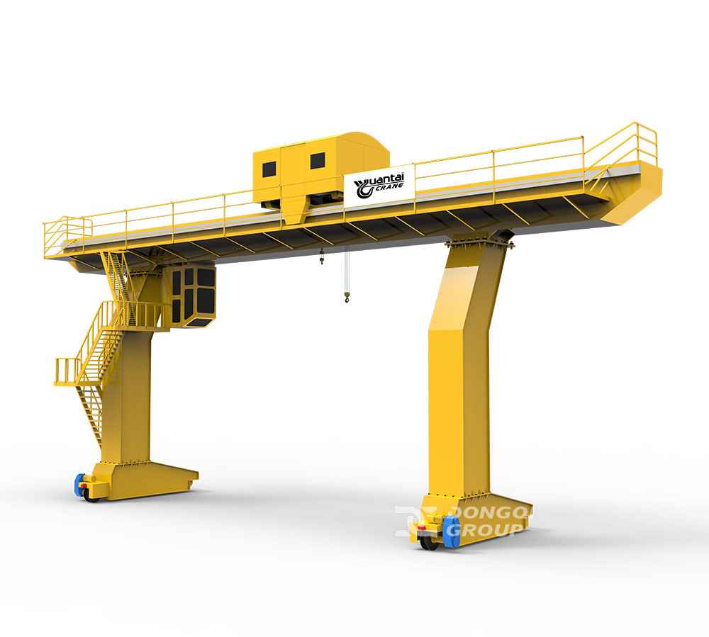
The L-type single girder gantry crane is a large industrial equipment. Its installation process involves multiple stages, each requiring strict adherence to construction specifications and technical standards. This scheme will detail the entire process from preliminary preparation to final debugging to ensure installation quality and operational safety. Before installation, it is necessary to clarify the structural characteristics, load parameters, and usage environment requirements of the crane. Structural characteristics include the crane’s dimensions, structural form, and rail type; load parameters include the crane’s rated load, lifting height, and operating speed; usage environment requirements include site conditions, climatic conditions, and safety clearances. These factors will all impact the installation and use of the crane and must be fully considered and defined.
After clarifying the above requirements, a construction plan conforming to the GB/T 14406 “Gantry Crane” standard needs to be developed. The construction plan should include the following: construction schedule, construction sequence arrangement, construction technology, and safety measures. The construction schedule should consider the actual on-site situation and construction conditions to ensure an orderly process; the construction sequence should follow the principle of ‘foundation first, then equipment’ and ‘main structure first, then attachments’ to ensure safety and quality during construction; construction technology and safety measures should propose specific solutions for potential risks and problems, ensuring safety and quality throughout the construction process.
The technical team must conduct a 3D review of the general assembly drawings, component drawings, and electrical schematics provided by the manufacturer. During this 3D review, the team should use professional 3D modeling software to meticulously check the drawings. Focus on verifying key data such as the connection nodes between the main girder and legs, and rail installation dimensions. This key data directly affects the installation accuracy and stability of the equipment and must be strictly reviewed. Furthermore, the technical team must check the positional deviation between the equipment foundation drawings and the embedded parts in the on-site concrete foundation. To ensure equipment stability and safety, the positional deviation between the equipment foundation drawings and the embedded parts must be checked. During checking, the axis deviation should not exceed ±5mm, and the elevation error should be controlled within ±3mm.
All welders, riggers, and electricians participating in the installation must hold special equipment operation certificates. These personnel are the main implementers of the equipment installation, and their skills and qualifications directly impact the installation quality and safety. Therefore, strict qualification audits must be conducted for all installation personnel to ensure they possess the necessary skills and qualifications. Additionally, the project manager must possess a hoisting machinery installation, alteration, and maintenance license. The project manager is responsible for coordinating and managing the entire installation process. Requiring the project manager to hold the relevant license ensures the project proceeds smoothly and complies with relevant regulations and standards. Conduct specialized lifting process training focusing on the asymmetric structural characteristics of the L-type main girder. Due to the asymmetric structure of the L-type main girder, special process measures are required during lifting. Therefore, specialized training for lifting personnel is necessary, clarifying the main girder center of gravity calculation method and anti-overturning measures. This training enhances the skill level and safety awareness of the lifting personnel, ensuring the lifting process is conducted smoothly and in compliance with standards.
Before formal installation begins, conduct a comprehensive and detailed survey and assessment of the installation site to ensure the work area meets safe construction requirements. Use total stations and other precision measuring equipment to accurately mark the baseline for rail installation, ensuring the rail laying position is precise. Simultaneously, thoroughly clear the rail laying area, removing all debris and obstacles within a 50 cm range to prevent installation errors or equipment damage caused by foreign objects. Furthermore, strictly inspect the power supply system to ensure sufficient capacity, stable provision of 380V±10%, 50Hz power supply, and ensure the grounding resistance value is less than 4Ω to guarantee the safe operation of the electrical system. For outdoor installation environments, pay extra attention to meteorological conditions, promptly install wind speed monitoring devices, and immediately stop aerial work in case of Level 8 or higher winds to ensure the safety of personnel and equipment.
Table: On-Site Environment Assessment and Clearing Checklist
| Assessment/Clearing Item | Specific Requirements and Standards | Tools/Equipment | Safety Measures | Related Standards/Norms |
|---|---|---|---|---|
| Rail Laying Area Clearing | Remove all debris and obstacles within 50 cm range | Total Station, Laser Theodolite | Prevent installation errors or equipment damage from foreign objects | _ |
| Power Supply System Check | Sufficient capacity, stable 380V±10%, 50Hz power, grounding resistance <4Ω | Insulation Resistance Tester | Ensure electrical system safe operation | GB/T 12325-2008 |
| Meteorological Condition Monitoring | Outdoor installation requires wind speed monitors; stop aerial work for Level 8+ winds | Wind Speed Monitoring Device | Ensure personnel and equipment safety | GB 50484-2008 |
| Rail Baseline Marking | Use precision measuring equipment to ensure accurate laying position | Total Station | Ensure rail geometry meets design requirements | GB 50308-2017 |
Table: Installation Equipment and Tools Preparation List
| Equipment/Tool Name | Function Description | Technical Parameters/Requirements | Application Scenario | Inspection Standard |
|---|---|---|---|---|
| 200-ton Truck Crane | Main lifting equipment for complex lifting tasks | Max. lifting capacity 200 tons | Lifting large rail components | GB/T 3811-2008 |
| 50-ton Crawler Crane | Auxiliary lifting, better ground adaptability | Max. lifting capacity 50 tons | Lifting in confined spaces or complex terrain | GB/T 14560-2016 |
| Hydraulic Torque Wrench | Precisely control tightening torque of high-strength bolts | Accuracy grade ±3% | Tightening rail connection bolts | GB/T 1228-2006 |
| Laser Theodolite | Measure and calibrate rail geometric dimensions | Angle measurement accuracy ≤2″ | Detecting rail straightness and verticality | JJG 414-2011 |
| Insulation Resistance Tester | Detect insulation performance of electrical system | Test voltage 500V/1000V | Power supply system safety acceptance | GB/T 18216.1-2021 |
During the installation process, a 200-ton truck crane is configured as the main lifting equipment to ensure efficient and safe operations; its powerful lifting capacity can handle various complex lifting tasks. Simultaneously, a 50-ton crawler crane is equipped for auxiliary lifting needs. This type of equipment offers better ground adaptability and flexibility, compensating for the limitations of truck cranes in specific environments. Furthermore, a range of professional tools such as laser theodolites, hydraulic torque wrenches, and insulation resistance testers are meticulously prepared. Among these, the laser theodolite is used for precise measurement and calibration of rail geometry to ensure straightness and verticality meet design requirements; the hydraulic torque wrench is used to precisely control the tightening torque of high-strength bolts, ensuring installation firmness; the insulation resistance tester is used to check the insulation performance of the electrical system, preventing electrical faults due to poor insulation. To ensure the accuracy and reliability of the torque wrenches, the used torque wrenches must have an accuracy grade not less than ±3%, meeting various high-precision task requirements. For high-strength bolts, a key connecting component, strict third-party re-inspection according to the GB/T 1228 national standard is mandatory. Only products that pass strict inspection can be used, thereby ensuring the quality and safety of the entire installation project.
The main girder is the core load-bearing component in the entire steel structure project. Its installation accuracy directly affects the stability and service life of the entire structure. During the installation of the main girder, the four-point lifting method is used for hoisting to ensure the balance of the main girder in the vertical direction. The angle between the sling and the horizontal plane is strictly controlled within the range of 60°-75° to avoid deformation or damage to the main girder caused by excessive or insufficient angles. After the main girder is positioned, use jacks for fine adjustment so that the horizontal camber of the main girder does not exceed S/2000 (S is the span), and the upward camber is controlled within the range of (0.9-1.4)S/1000. These adjustment measures ensure that the main girder has sufficient stiffness and stability when bearing loads.
After the main girder installation is completed, welding operations are performed. The welding process must comply with the JB/T 5000.7 standard to ensure welding quality and safety. Welds undergo 100% ultrasonic testing to detect any potential weld defects such as cracks, lack of fusion, slag inclusions, etc. These non-destructive testing measures can promptly identify and repair potential safety hazards, ensuring the long-term stability and reliability of the main girder.
The legs are the supporting components in the steel structure project. Their verticality deviation must be ≤ H/2000 (H is the leg height). During installation, use a total station for monitoring in two directions to ensure installation accuracy and stability of the legs. The flatness of the contact surface between the lower cross beam and the rail must be ≤1mm/m to ensure good contact and uniform force distribution between the lower cross beam and the rail. Simultaneously, the bolt preload must reach within ±5% of the design value to ensure the tightness of the bolted connection meets the design requirements. To maintain lubrication and reduce friction loss, apply molybdenum disulfide grease to all hinged parts.
The installation and wiring of the electrical system are crucial links in the steel structure project, directly related to the normal operation and safety of the equipment. Cable laying must follow GB 50217 specifications to ensure reasonable cable routing, reliable fixation, and compliance with safety requirements such as fire prevention and insulation. Power cables and control cables are arranged in separate layers to avoid interference and safety hazards. Install reactors at the output end of the frequency converter to effectively suppress voltage fluctuations and electromagnetic interference, improving system stability and reliability. The motor insulation resistance value must be ≥1MΩ to ensure good insulation performance and safety during motor operation. The triggering position of the limit switch must be 100-150mm ahead of the mechanical stop to ensure the equipment stops accurately at the predetermined position and avoid overload and other safety hazards.
The installation and debugging of safety devices are critical links in the steel structure project, ensuring the safe operation and service life of the equipment. Perform three simulated action tests on the lifting height limiter, with errors not exceeding ±50mm, to ensure the accuracy and reliability of the limiter. Calibrate the overload limiter at 110% of the rated load, and ensure the response time of the audible and visual alarm system is ≤2 seconds, so that the equipment can promptly alarm and take corresponding measures under abnormal conditions such as overload. The compression test for the buffer at the end of the trolley travel must reach over 90% of the design value to ensure the buffer can effectively absorb energy and protect the structure from damage upon impact. These measures can effectively improve equipment safety and service life, providing strong support for the smooth progress of the project.
During the installation of hoisting machinery, a series of strict quality inspection standards must be implemented to ensure installation accuracy, stability, and safety. Taking a certain model crane as an example, the static load test at the mid-span of the main girder must maintain 1.25 times the rated load for 10 minutes. During this period, structural components must show no permanent deformation, reflecting that the structural strength and stiffness meet the design requirements. The dynamic load test is performed with 1.1 times the rated load to complete the full range of motions for all mechanisms. The braking slip distance must not exceed V/100 (V is the rated speed), ensuring reliable braking performance during normal operation. Furthermore, no less than 3 safety wraps of wire rope must remain on the drum. This is to ensure that during long-term use, the wire rope will not cause safety hazards due to overstretching or wear.
After the hoisting machinery installation is completed, acceptance must be carried out according to the specified process. First, compiling a complete acceptance file is an essential step. This file should include detailed information such as weld inspection reports, electrical test records, and load test videos. These documents can comprehensively reflect the installation quality and performance of the hoisting machinery, providing a strong basis for subsequent acceptance work. Next, the special equipment supervision and inspection agency will conduct on-site confirmation of the hoisting machinery, performing strict inspections on various performances of the equipment. Once the equipment is confirmed to meet the design requirements and relevant standards, the “Hoisting Machinery Safety Technical Supervision Certificate” will be issued. Finally, the user unit must archive 13 statutory documents including the equipment factory certificate and installation notification. These documents not only aid in the management and maintenance of the hoisting machinery but also provide necessary support for subsequent supervision and review.
After completing the crane installation, no-load debugging and functional testing must first be conducted to ensure the equipment operates under normal conditions. For the trolley travel mechanism, a 20m round-trip test is performed to verify its operational stability and accuracy. During this process, staff will carefully check the gap between the wheel tread and the rail, ensuring it does not exceed 2mm, thus guaranteeing that the travel mechanism does not vibrate or jam due to excessive clearance during operation. The hoisting mechanism requires three full cycles of lifting and lowering to test its lifting capacity and precision. During lifting and lowering, measuring the braking distance is key, ensuring it does not exceed 105% of the rated value, which helps prevent brake failure in emergencies. The remote control is an important component of the crane, and the response time difference of its various buttons also needs strict testing. During debugging, technicians measure the response time of each button using professional equipment, ensuring the difference is less than 0.5 seconds, thus guaranteeing that operators can accurately and promptly execute various operations during remote control.
After passing the no-load debugging and functional testing, load debugging and performance evaluation need to be conducted next. Graded loading up to the rated load is an important part of load debugging. During this process, technicians gradually increase the load weight and measure the deflection of the main girder under load. According to relevant specifications, the main girder deflection value should not exceed S/700 (S is the calculated span of the main girder) to ensure the main girder does not undergo excessive deformation under load, thereby ensuring normal equipment operation and safety. Stable operation of the variable frequency speed control system within the 10%-100% speed range is another key point of load debugging. Technicians adjust the frequency converter parameters to operate the crane at different speeds and observe its operational status. During this process, technicians need to ensure the crane remains stable during acceleration, deceleration, and constant speed operation, without abnormal vibration or noise. The temperature rise of the gearbox not exceeding 45K after continuous operation for 1 hour is another important indicator of load debugging. Technicians monitor the temperature change of the gearbox during continuous equipment operation, ensuring it does not overheat leading to performance degradation or damage under prolonged working conditions.
When setting up or maintaining aerial work platforms, all work must be conducted under strict safety protection measures. Specifically, set up sturdy guardrails with a height of no less than 1.2 meters at the edges of the work platform to prevent accidental falls; for potential risk areas such as holes and openings, they must be covered with anti-slip steel plates with a thickness of no less than 5mm to eliminate fall risks and enhance the stability of the work surface. During lifting operations, set up clearly marked hard isolation zones within the work radius, post warning signs, and strictly prohibit non-operating personnel from entering the area. Before starting work each day, carefully inspect lifting tackles, focusing on wear conditions, and strictly implement the scrapping standards specified in the GB/T 5972 national standard to ensure lifting equipment is in good working condition and avoid safety hazards caused by equipment aging or damage.
To respond to possible emergencies and ensure rapid and orderly handling when accidents occur, a comprehensive emergency plan system should be established. Specific measures include: establishing an emergency team led by the project manager, comprising safety officers, medical personnel, and other professionals responsible for coordinating responses to various emergencies. This team must be equipped with advanced hydraulic rescue jacking devices and first aid kits to ensure rapid rescue operations can be launched in emergencies; for major safety accidents such as main girder overturning, pre-establish two emergency evacuation routes in different directions to ensure personnel can evacuate to safety in the shortest possible time; simultaneously, all emergency plans must not only be filed with the local Work Safety Supervision Administration but also undergo quarterly simulation drills to verify the feasibility and effectiveness of the plans and improve practical response capabilities.
Contact our crane specialists
Send us a message and we will get back to you as soon as possible.