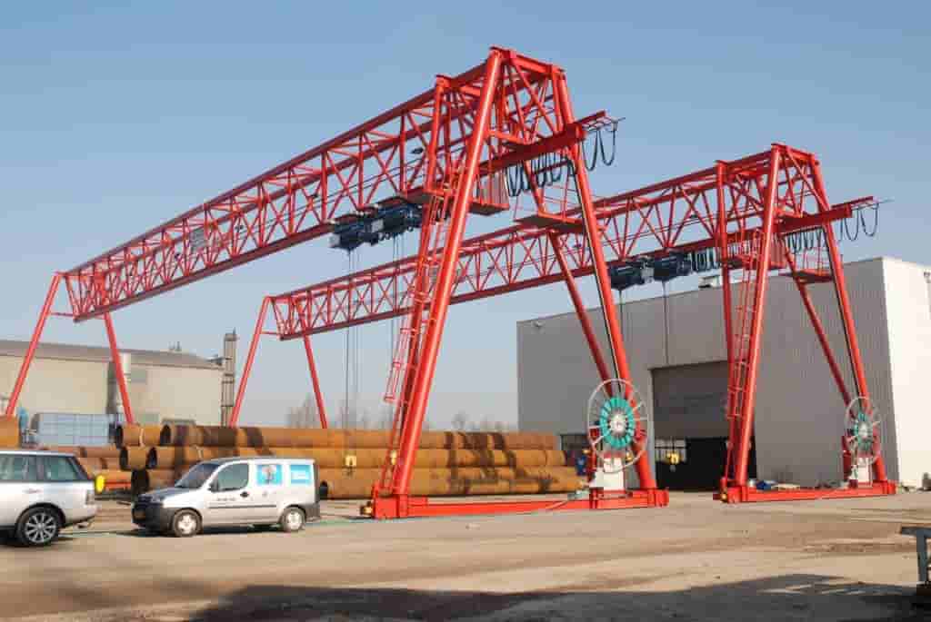
Span (Lk): Typical value: 20m (adjustable according to requirements);
Lifting Height (H): 10m;
Working Class: A3 (medium frequency of use).
II. Load Calculation
Static Load
Deadweight load: Includes the weight of the main beam, outriggers, electric hoist, etc., and must be calculated based on the material density and cross-sectional dimensions (e.g., Q345B low-alloy steel).
Lifting load: 10 tons rated load, considering a dynamic load factor of 1.1 (GB3811 requirements).
Dynamic load
Operating inertia force: Horizontal loads generated by acceleration and braking forces;
Wind load: Operating wind pressure is calculated as 250 Pa, and adjustments must be made to local wind pressure during non-operating conditions.
Load combination
Type II load combination: Used for main beam strength calculation (static load + dynamic load + wind load).
III. Main beam design calculation
Sectional characteristics
For truss main beams using box or H-section sections, calculate the moment of inertia (Ix, Iy) and bending modulus. For example, for a design, Ix = 2224147663.108 mm⁴.
Material selection: Q345B steel, yield strength 345 MPa, elastic modulus E = 210 GPa.
Strength and deflection verification
Strength: Calculate the bending normal stress based on the maximum bending moment (mid-span), which must meet the allowable stress (σ ≤ [σ]). Deflection: Mid-span deflection fmax = ML²/(8EI), allowable value ≤ L/400 (≤ 50mm for a 20m span).
Local Stability
Stiffener Arrangement: Prevent web buckling. Spacing is determined based on plate thickness and load.
IV. Outriggers and Connection Nodes
Outrigger Calculation
Compressive Stability: Verify slenderness ratio using Euler’s formula, maintaining λ ≤ 150.
Foundation Reaction: Calculate track beam bearing capacity based on wheel load distribution, with base coefficient k = 5.6 × 10⁴ kN/m³.
Joint Design
High-Strength Bolted Connections: Friction-type bolts are used between the main beam and the outriggers. Shear bearing capacity must meet load requirements.
V. Wind and Seismic Resistance Measures
Wind Resistance Design
Wind pressure in operating state is 250 Pa. In non-operating state, verify according to the local 50-year wind pressure.
Add windbreak cables or anchoring devices.
Seismic Requirements
Verify horizontal seismic effects according to the “Code for Seismic Design of Buildings,” focusing on checking the connection between the outriggers and foundation.
VI. Calculation Output
A complete calculation report should include:
Design parameters and code references;
Load calculation tables and combination results;
Strength, stiffness, and stability verification of the main beam and outriggers;
Joint details and bolt selection;
Wind resistance and foundation design specifications.
Contact our crane specialists
Send us a message and we will get back to you as soon as possible.