An overview of the manual of the BZ fixed-column jib crane
The BZ fixed-column jib crane is a special lifting equipment designed according to user needs. It has the advantages of novel, reasonable and simple structure, convenient operation and use, flexible rotation, and large working space. It is an energy-saving and efficient material lifting equipment. It can be widely used in production lines, assembly lines and machine tools in factories, mines and workshops, as well as in warehouses, docks and other occasions for heavy lifting.
This machine is composed of a column, a rotary arm and an electric chain hoist. The lower end of the column is fixed on the concrete foundation, and the swing arm rotates, which can be rotated according to user requirements. The slewing part is divided into manual slewing and electric slewing (the cycloidal pinwheel reducer is installed and the upper or lower pallet drives the rotating tube to rotate the arm). The electric chain hoist is installed on the jib track for lifting heavy objects.
| Rated lifting capacity (t) | 0.25, 0.5, 1, 2, 3, 4, 5 |
| Lifting height (m) | 2, 2.5, 3, 3.5, 4, 4.5, 5, 5.5, 6 |
| Lifting speed (m/min) | 8/2, 4/1, 10/2.5, 5/1.25, 2.6/0.7 |
| Running speed (m/min) | 14 |
| Radius of gyration | 2, 3, 4, 5, 6 |
| Rotation angle | Degree≤360° |
| Swing speed | Manual or 0.8r/min (electric) |
| Foot size (attached) |

of the electric chain hoist: see the attached electric hoist “Operation and Maintenance Manual”.
note:
For the convenience of transportation, the machine is disassembled and packaged, and the user installs it by himself according to the method introduced in this book (see “Five” installation)
The lifting methods of beams and columns are shown in Figure 2 and Figure 3.


Before installation, check the product and technical documents according to the packing list for any loss of life, bending and torsion deformation of the arm beam, and corrosion of the shaft during transportation. Bumps should be corrected or restored separately, and rotating parts such as shafts and bearings should be cleaned and lubricated every six months.
1. Column installation should keep the column vertical to the ground. The anchor plate screws should be tightened firmly without any looseness. The floor and the foundation should fit well. If equipped with an electric hoist, the foundation should be embedded with cables and grounding facilities. The cable is led out from the center of the foundation, and the grounding resistance shall not be greater than 4 ohms.
2. Installation of jib beam
For the installation of the jib beam, please proceed in the following order.

After the above steps are completed, the integral hoisting of the jib beam can be carried out.
When hoisting, after lifting according to the lifting method specified in Figure 2, align the shaft with the bearing hole on the top of the column, and slowly lower the roller against the raceway of the column. After adjusting the proper position, use the washer, round nut and round nut non-return washer to fix the shaft through the side hole on the upper part of the column. Then drag the slip ring with one hand, pass the side hole on the upper part of the column, and set it on the beam shaft. (See Figure 6)
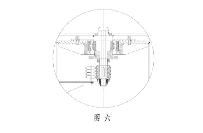
Then, connect the wires hanging from the perimeter of the beam to the terminal on the collector ring, and connect the carbon brushes to the power switch at the lower part of the column with wires, and finally fix the carbon brush holder on the inner wall of the column. Adjust the sliding plate to keep good contact with the copper ring on the collector ring. Turn on the power and start the test run.
note:
After assembly and assembly of the swing arm beam and column, it should be ①The rollers and the raceway should fit well, ②The swing arm can rotate 360° around the column flexibly, ③Adjust the adjustment shims so that the end of the swing arm beam reaches the upper deflection ≥ R/250 (R is the radius of gyration).
After all the installations are completed, the test run can be carried out.
Before the test run, add 30# mechanical oil into the rotary reducer to the middle position of the oil standard (change the oil once every six months).
During the test run, first press the buttons to check whether the running direction is consistent with the indicator symbol of the flashlight door. If not, you can adjust the consistency.
No-load test: The electric hoist should run smoothly when running left and right on the beam and lifting up and down, and the jib beam should be flexible and stable when rotating, and should stop at any position so as not to slip by itself, and the outer end has a certain upper deflection F ≥ R/250 (R is the radius of gyration).
Rated load test: Under the condition of rated load, the crane hook is at the extreme position of the farthest away from the column to lift heavy objects and perform a 360° rotation (electric or manual). More than F≥R/125mm.
In order to prevent accidents caused by operation failure, a switch that can cut off the power supply in an emergency must be installed near the crane. The crane cable should use the YZ-500V medium-sized rubber cable specified by JB678-77 (one of which is grounded, so four Core cable).
Contact our crane specialists
Send us a message and we will get back to you as soon as possible.