HomeGantry crane → Overall Design Scheme for 16t-22m Box-Type Single Girder Gantry Crane

Overall Design Scheme for 16t-22m Box-Type Single Girder Gantry Crane

I. Design Overview

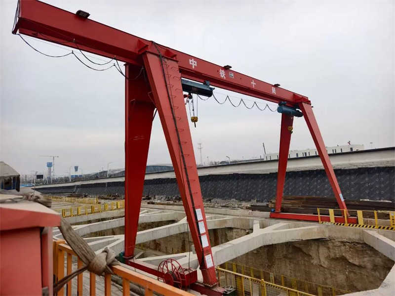
The 16t-22m box-type single girder gantry crane is a medium-duty lifting equipment suitable for operations such as railway handling and open-air material loading and unloading. This design aims to meet the modern industrial demand for efficient, stable, and cost-effective material handling. Through reasonable structural design and computational analysis, it ensures reliable operation under the conditions of a 16-ton rated capacity and a 22-meter span. Compared to a double girder structure, the single girder design offers advantages such as simple structure, light weight, and low manufacturing cost, making it particularly suitable for medium-capacity operations.

The box-type single girder gantry crane mainly consists of core components like the main girder, legs, end beams, trolley, and traveling mechanisms. It features a box-section main girder design, characterized by a simple and practical structural form, easy operation, and convenient maintenance. According to the work duty classification, this design belongs to Class A3, suitable for working environments with intermittent but somewhat frequent use. The main girder adopts an off-track box girder structure, optimizing the overall crane weight while ensuring sufficient strength and stiffness.

16t-22m Box-Type Single Girder Gantry Crane

II. Design Specifications and Standards

This design strictly adheres to the following national and industry standards:

  • GB/T3811-2008 “Design Rules for Cranes”: Specifies the basic design principles, load calculation methods, and safety requirements for cranes.
  • JB/T5663-2008 “Electric Hoist Gantry Cranes”: Specific technical requirements for electric hoist gantry cranes.
  • Class A3 Work Duty Standard: Conforms to medium work intensity requirements, suitable for working environments with relatively short daily usage time and general loading conditions.

The design process also references technical parameters and engineering practical experience of similar domestic and international products, ensuring the design outcome meets standard requirements while possessing good practicality and economy. The electrical system uses a 380V/50Hz power supply, with a control voltage of a safe 36V, complying with industrial site electrical safety standards.

III. Main Technical Parameters

The main performance parameters of the 16t-22m box-type single girder gantry crane are as follows:

  1. Basic Parameters:
    • Rated Capacity: 16 tons (main hook)
    • Span: 22 meters (adjustable within a certain range according to user requirements)
    • Work Duty: Class A3, suitable for general material handling operations.
    • Lifting Height: Standard design 10 meters (adjustable from 3 to 18 meters range according to user requirements).
  2. Operating Speeds:
    • Crane Traveling Speed: 20 m/min (variable frequency speed control optional)
    • Trolley Traveling Speed: 20-30 m/min (determined by the accompanying hoist model)
    • Hoisting Speed: Conventional design 8 m/min (adjusted according to the accompanying hoist model)
  3. Structural Parameters:
    • Main Girder Type: Off-track box-type single girder structure
    • Leg Type: L-type or C-type leg design (selected based on user space requirements)
    • Cantilever Length: Optional single or double cantilever design, standard design is non-cantilever.
    • Rail Model: QU70 or QU80 grade crane-specific rails.
  4. Electrical Parameters:
    • Power Supply: Three-phase AC 380V, 50Hz
    • Control Method: Optional floor pendant control, wireless remote control, or cabin control.
    • Control Voltage: Safe voltage 36V.
  5. Environmental Adaptability:
    • Operating Ambient Temperature: -20℃ ~ +40℃
    • Maximum Wind Resistance: Can reach 60 m/s in non-working state (designed based on user region wind load).

IV. Detailed Structural Design

1. Main Girder Design

The main girder, as the core load-bearing component of the crane, directly affects the safety and reliability of the entire machine. This design adopts an off-track box-type single girder structure with the following characteristics:

Section Design:

  • Box Section Dimensions: Determined by calculation, typically height 1000-1200mm, width 600-800mm.
  • Top Flange Plate Thickness: 14-16mm,withstands main compressive stress.
  • Bottom Flange Plate Thickness: 12-14mm,withstands tensile stress.
  • Web Plate Thickness: 8-10mm, with longitudinal stiffeners added to improve stability.
  • Rail Installation Method: Off-track design, rails installed on one side of the main girder’s top flange to reduce torsional loads.

Strength and Stiffness Calculations:

The main girder design must meet the following calculation requirements:

  • Vertical Static Stiffness: ≤ S/800 (S is the span)
  • Vertical Dynamic Stiffness: ≤ S/1000
  • Horizontal Stiffness: ≤ S/2000
  • Strength Safety Factor: ≥ 1.48 (as required by GB/T3811)

Manufacturing Process:

  • Segmented Fabrication: For ease of transportation, the 22-meter main girder is fabricated in 2-3 segments, connected on-site with high-strength bolts.
  • Welding Process: Uses submerged arc automatic welding to ensure quality of main welds, with stress relief treatment after welding.
  • Pre-camber: Main girder has a pre-camber of approximately S/1000 to counteract deflection under working loads.

2. Leg Design

The legs are key components connecting the main girder to the lower traveling mechanisms. This design offers two leg forms for selection:

L-Type Legs:

  • Structural Feature: Right-angle L-type design, simple manufacturing, easy installation.
  • Advantages: Good force-bearing performance, low manufacturing cost.
  • Disadvantage: Relatively smaller cargo passage space.

C-Type Legs:

  • Structural Feature: Inclined or curved design, providing larger passage space.
  • Advantage: Suitable for large cargo passage, high space utilization.
  • Disadvantage: Complex structure, higher manufacturing cost.

Leg Structure Calculation:

  • Rigid Leg: Rigidly connected to the main girder,withstands vertical and horizontal loads.
  • Flexible Leg: Allows some deformation to release thermal stress.
  • Leg Height: Determined by the lifting height, typically 8-10 meters.
  • Section Design: Box section, dimensions typically around 600×600mm, plate thickness 10-12mm.

3. End Beams and Traveling Mechanism

End beams are components connecting the legs on both sides and supporting the crane traveling mechanism:

End Beam Design:

  • Box section structure, connected to the main girder and legs with high-strength bolts.
  • Houses the crane travel drive unit and driven wheel set.
  • Equipped with buffers and anti-collision devices to ensure travel safety.

Crane Traveling Mechanism:

  • Drive Method: “Three-in-one” drive unit (integrated motor, brake, reducer).
  • Drive Power: 4×3kW (determined by calculation).
  • Wheel Diameter: Approximately Φ400mm, using alloy steel forgings.
  • Rail Model: QU70 or QU80 grade crane-specific steel rails.

4. Trolley and Hoisting Mechanism

This design uses an electric hoist as the hoisting mechanism, running directly on the lower flange of the main girder:

Trolley Configuration:

  • CD1/MD1 type electric hoist (selected based on user requirements).
  • Travel Method: Runs along the lower flange of the main girder, using an angular trolley frame.
  • Wheel Set: Double flanged design to prevent derailment.
  • Safety Devices: Equipped with hoisting height limiter, overload limiter, etc.

Hoisting Mechanism Parameters:

  • Capacity: 16 tons (main hook).
  • Hoisting Speed: 8 m/min (conventional design).
  • Motor Power: 13kW (adjusted based on lifting height).
  • Wire Rope: 18×7+FC-16mm, high-strength rotation-resistant type.

V. Calculations and Verification

1. Load Calculation

The crane design must consider the following load combinations:

  • Regular Loads: Self-weight load, hoisting load, horizontal inertial loads, etc.
  • Occasional Loads: Sideways forces from skew running, collision loads, etc.
  • Special Loads: Seismic loads, wind resistance loads, etc.

Main Girder Load Combinations:

  • Condition 1: Self-weight + Rated Load (Basic Loads)
  • Condition 2: Self-weight + Rated Load + Horizontal Inertial Force (Operating Condition)
  • Condition 3: Self-weight + 25% Rated Load + Non-working State Wind Load (Non-working State)

2. Main Girder Strength and Stiffness Calculation

Strength Calculation:

  • Normal Stress Calculation: σmax = Mmax/Wz ≤ [σ]
  • Shear Stress Calculation: τmax = Qmax·S/(I·t) ≤ [τ]
  • Combined Stress Calculation: Considering the combination of normal and shear stresses.

Stiffness Calculation:

  • Vertical Static Deflection: f ≤ S/800
  • Vertical Dynamic Deflection: f ≤ S/1000
  • Horizontal Deflection: f ≤ S/2000

Stability Calculation:

  • Global Stability: Ensured by controlling aspect ratio and setting stiffeners.
  • Local Stability: Controlled by plate width-to-thickness ratio, setting longitudinal and transverse stiffeners.

3. Leg Calculation

Legs, as beam-column members, require the following calculations:

  • Strength Calculation: σ = N/A + M/W ≤ [σ]
  • Stability Calculation: N/(φ·A) ≤ [σ] (considering bending moment influence).
  • Leg to Main Girder Connection Joint Calculation: High-strength bolt connection calculation and gusset plate strength calculation.

4. Wind Resistance Calculation

According to GB/T3811 requirements, wind resistance in the non-working state must be checked:

  • Wind Load Calculation: Fw = Cw·Pw·A
  • Anti-overturning Stability: Stabilizing moment under wind action ≥ Overturning moment × 1.1

VI. Manufacturing and Installation Process

1. Main Component Manufacturing Process

Main Girder Manufacturing:

  1. Cutting: CNC cutting to ensure dimensional accuracy.
  2. Assembly: Special fixtures ensure box section dimensions.
  3. Welding: Submerged arc automatic welding for main welds, manual welding for repairs.
  4. Correction: Flame straightening for welding deformation.
  5. Machining: Milling connection end faces.

Leg Manufacturing:

  1. Segmented Manufacturing: Divided into upper and lower sections.
  2. Welding: Strictly control welding deformation.
  3. Machining: Milling connection flange faces.

2. On-site Installation Plan

Typical installation procedure for the 16t-22m box-type single girder gantry crane:

  1. Preparation:
    • Rail installation acceptance (rail gauge deviation ≤ ±5mm, elevation difference ≤ 10mm).
    • Component unpacking inspection.
    • Preparation of construction machinery and tools (mobile crane, tools, etc.).
  2. Installation Sequence:
    1. Leg Installation: Install rigid leg first, then flexible leg.
    2. Main Girder Installation: Hoist segments, connect at height (requires temporary support).
    3. Trolley Installation: Install electric hoist after main girder is positioned.
    4. Electrical System Installation: Cable laying, electrical equipment installation.
    5. Safety Device Installation: Limit switches, buffers, etc.
  3. Commissioning and Acceptance:
    • No-load Test: Run all mechanisms through full travel, check for abnormalities.
    • Static Load Test: 1.25 times rated load test.
    • Dynamic Load Test: 1.1 times rated load test.

VII. Safety Protection Devices

To ensure safe crane operation, this design is equipped with a comprehensive safety protection system:

  1. Electrical Protection:
    • Short Circuit Protection: Circuit breaker protection.
    • Overcurrent Protection: Motor overload protection.
    • Undervoltage Protection: Protection against sudden power loss.
    • Zero Position Protection: Prevents misuse.
  2. Mechanical Safety Devices:
    • Hoisting Height Limiter: Prevents overwinding.
    • Travel Limit Switches: Limit extreme positions of crane and trolley travel.
    • Buffers: Absorb impact energy.
    • Windproof Devices: Rail clamps or anchor devices.
  3. Monitoring System:
    • Load Limiter: Prevents overload operation.
    • Tilt Alarm: Monitors crane tilt status.
    • Anemometer: Monitors ambient wind speed.

VIII. Technical and Economic Analysis

1. Design Advantages

This 16t-22m box-type single girder gantry crane design has the following technical advantages:

  • Simple Structure: Single girder design reduces self-weight by about 20%-30% compared to double girder structure.
  • Easy Manufacturing: Box girder has good manufacturability, suitable for batch production.
  • Quick Installation: Segmented design facilitates transportation and on-site assembly.
  • Easy Maintenance: Electric hoist is highly standardized, resulting in low maintenance costs.
  • High Space Utilization: Compared to overhead cranes, it does not occupy internal workshop space.

2. Economic Analysis

Compared to similar products, this design offers the following economic benefits:

  • Low Material Cost: Single girder structure saves about 15-20% in steel.
  • Less Manufacturing Labor: Box girder welding process is mature, high efficiency.
  • Reduced Installation Costs: Segmented design reduces usage time of large cranes.
  • Low Operating Energy Consumption: Lightweight design reduces power requirements.

IX. Innovative Design Points

This 16t-22m box-type single girder gantry crane design incorporates innovations and optimizations in the following aspects:

  1. Modular Design:
    • Main components like main girder and legs use modular segmented design.
    • Facilitates serialization and expansion, span adjustable to 18-30 meter range.
    • Capacity expandable to 5-20 ton series.
  2. Optimized Connection Structure:
    • High-strength bolted connections replace traditional welded flange connections.
    • Reduces on-site welding workload, improves installation quality.
  3. Lightweight Design:
    • Optimizes main girder cross-sectional dimensions through finite element analysis.
    • Reduces structural self-weight while ensuring strength and stiffness.
  4. Intelligent Control:
    • Optional variable frequency control system for smooth starting and stopping.
    • Remote control function improves operational convenience.

X. Application Prospects and Expanded Design

The 16t-22m box-type single girder gantry crane has broad application prospects:

  1. Typical Application Areas:
    • Railway Freight Yards: Container, bulk cargo loading/unloading operations.
    • Power Equipment: Power plant equipment installation and maintenance.
    • Building Materials Industry: Prefabricated component handling and stacking.
    • Logistics Warehousing: Large warehouse material handling.
  2. Expanded Design Directions:
    • Double Cantilever Design: Increases operational coverage area.
    • Electromagnetic Lifting Beam: Suitable for steel material handling.
    • Grab Bucket Device: For bulk material loading/unloading operations.
    • Variable Frequency Control: Improves running smoothness.
  3. Series Development:
    • Capacity Series: 5t, 10t, 16t, 20t.
    • Span Series: 18m, 22m, 26m, 30m.
    • Work Duty: A3-A5 (selected based on usage frequency).

Conclusion

This design for the 16t-22m box-type single girder gantry crane, through reasonable structural selection and computational verification, achieves an optimized design in the medium capacity range. The box-type single girder structure balances strength, stiffness, and economic requirements. Combined with standardized traveling and hoisting mechanisms, it forms a complete design scheme. This design features a simple structure, easy installation, and convenient operation and maintenance, making it particularly suitable for open-air work sites like railway handling and power equipment installation. Through the modular design concept, this product can be expanded into a series to meet different user needs. The design process strictly follows relevant national standards and specifications, ensuring product safety and reliability, and it has good market application prospects.

  Contact our crane specialists


Send us a message and we will get back to you as soon as possible.

    Send Your Needs