Home → News → Overall design scheme of 10-ton bridge crane
Overall design scheme of 10-ton bridge crane
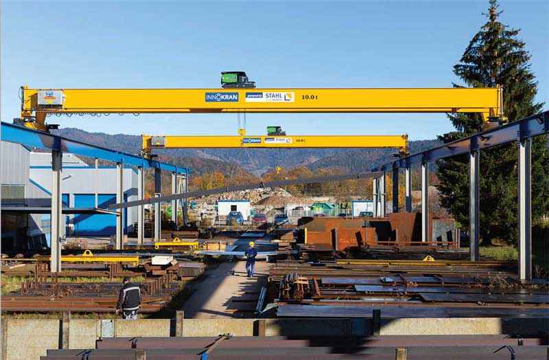
This design addresses the material handling needs of industrial production and proposes a comprehensive overall design for a 10-ton bridge crane. As indispensable material handling equipment in modern industry, the performance of bridge cranes is directly related to production efficiency and operational safety. Currently, many factories in my country still use outdated equipment based on outdated foreign technology, which no longer meets the functional and safety requirements of modern industry. This paper comprehensively discusses the crane’s key technical parameters, structural design, mechanism design, and safety device configuration, focusing on cost optimization and layout rationalization, ultimately achieving the design of a technologically advanced 10-ton bridge crane with an M6 working class.
Design Overview and Research Significance
Bridge cranes are essential equipment for mechanizing and automating production processes in modern industry, improving material handling conditions, and increasing labor productivity. They utilize the space beneath the bridge to lift materials, unhindered by ground-based equipment. They are widely used in indoor warehouses and factory buildings. With the rapid development of economic development and the increasing demand for mechanization and automation in industrial production, technological innovation in bridge cranes has become increasingly important. Many Chinese factories still use bridge cranes based on outdated foreign technology, some even dating back to the 1970s and 1980s. These equipment, in terms of quality and functionality, cannot meet the growing demands of industry. In particular, they fall significantly short of modern industrial standards in terms of reliability, safety, and ease of operation. Therefore, minimizing costs, optimizing layout, and modernizing functionality of bridge cranes through innovative design have become key research topics.
This design focuses on small to medium-sized bridge cranes in the 10-ton tonnage range, which are representative and widely applicable. Cranes in this load range are most frequently used in machining, assembly workshops, and material yards. Compared to traditional designs, this solution emphasizes the following aspects:
Structural Optimization: Through scientific calculations and modern design methods, material usage is minimized while ensuring strength and rigidity, reducing manufacturing costs.
Standardized Design: Standard components and universal designs are used whenever possible to improve equipment maintainability and facilitate component replacement.
Safety and Reliability: Designed in strict accordance with relevant national standards and equipped with comprehensive safety protection devices, this approach ensures safe and reliable operation.
Easy Maintenance: The structural layout incorporates ease of maintenance to reduce maintenance costs throughout the equipment’s lifecycle.
The 10-ton bridge crane designed in this project utilizes a box-type double-girder structure. The double-girder bridge frame consists of two box-shaped main girders and two transverse end beams. A hoist trolley operates on the bridge, enabling the lifting and horizontal transport of various objects. This structural design offers advantages such as high rigidity, strength, and smooth operation, making it particularly suitable for medium-tonnage lifting needs.
Determination of Key Technical Parameters
The technical parameters of a bridge crane are quantitative indicators of its operating performance and form the basis of its design. Proper determination of these parameters directly impacts the crane’s operating capacity, safety, and economic efficiency. Based on actual industrial production needs and reference to relevant design specifications, the key technical parameters of this 10-ton bridge crane are determined as follows:
Basic Performance Parameters
Rated lifting capacity: 10 tons (main hook). This is the basic load parameter for crane design and refers to the maximum weight of material the crane can lift under normal operating conditions, including the weight of the lifting device. Depending on usage requirements, an auxiliary hook (typically 3-5 tons) may be considered to enhance operational flexibility.
Lifting height: 12-16 meters. This parameter refers to the vertical distance between the highest and lowest working positions of the spreader. Considering the actual height of most industrial plants, this design establishes a standard lifting height of 12 meters, which can be expanded to 16 meters based on user requirements.
Span: 16-22.5 meters. The span is the horizontal distance between the centerlines of the crane’s wheels at each end of the crane’s beams and must be compatible with the plant structure. This design offers a variety of span options to suit different factory requirements. The standard span is 22.5 meters, which can be adjusted based on actual needs.
Mechanism Operating Speed
Hoisting Speed: 10-13.3 m/min, refers to the hook’s rising speed when unloaded. This speed range ensures both efficient operation and smooth starting and stopping, as well as accurate positioning. For precision assembly applications, a dual-speed or variable frequency speed control system can be configured.
Trolley Operating Speed: 40-43.8 m/min, refers to the speed at which the trolley moves along the main beam rails. Excessive speed can cause load swing, while too low a speed can affect efficiency. This parameter has been dynamically optimized.
Trolley Operating Speed: 80-116.8 m/min, refers to the speed at which the entire crane moves along the factory rails. Higher speeds improve efficiency when moving long distances, but require a sound speed control and braking system.
Other Important Parameters
Duty Class: M6, which indicates the severity of a crane’s workload and is determined according to ISO standards. The M6 rating indicates a crane with a medium intended use (Utilization Class U4, Load Condition Q3), suitable for busy workshops and warehouses.
Trolley track gauge: 2 meters, referring to the distance between the centerlines of the trolley wheels. This parameter affects the trolley’s stability and maneuverability.
Gross machine weight: Approximately 23.5 tons, representing the crane’s own weight and impacting the load-bearing requirements of the factory structure.
Table: Summary of Main Technical Parameters of a 10-ton Bridge Crane
Parameter Category
Specific parameters
Numerical range
Remark
Basic parameters
Rated lifting capacity
10t
Main hook
Lifting height
12-16m
Customizable
Span
16-22.5m
Commonly used 22.5m
Speed Parameters
Lifting speed
10-13.3m/min
Trolley running speed
40-43.8m/min
Crane running speed
80-116.8m/min
Other parameters
Work Level
M6
Trolley gauge
2m
Total weight of the machine
≈23.5t
These technical parameters were determined by comprehensively considering industry standards, usage requirements, and safety factors, providing clear objectives and constraints for subsequent detailed design. In actual application, appropriate adjustments and optimizations will be required based on the specific usage environment and special requirements.
Overall Structural Design
The structural design of a bridge crane is the foundation of its mechanical performance. A sound structural design ensures the crane’s strength, rigidity, and stability under various operating conditions. This 10-ton bridge crane utilizes a box-type double-girder structure. This structure consists of two box-shaped main beams and two transverse end beams forming a double-girder bridge. A hoist trolley operates on the bridge, enabling lifting and horizontal transport of various objects. Compared to single-girder structures, the box-type double-girder structure offers superior rigidity and strength, making it particularly suitable for medium-tonnage lifting needs.
Girder Structure Design
The bridge is the primary load-bearing component of a bridge crane and consists of the main beam, end beams, walkway, and railings. Its design must fully consider mechanical strength and stability:
Girder Design: An off-track box-type girder structure is employed, with the trolley tracks mounted on the sides of the main beam’s upper flange. The main beam is welded together into a box-shaped structure consisting of upper and lower deck plates and two side webs. Longitudinal and transverse stiffeners are installed internally to enhance local stability. The box-type girder boasts mature manufacturing technology and high bending and torsional rigidity. The main beam design must meet the following requirements:
Vertical static stiffness: The vertical deflection of the main beam under rated load should not exceed 1/800 of the span.
Horizontal static stiffness: The horizontal displacement of the main beam should not exceed 1/2000 of the span.
Dynamic stiffness: The vibration of the main beam during operation should be controlled within safe limits.
End beam design: The end beam connects the two main beams to form an integral bridge frame and houses the trolley running mechanism. The end beam also adopts a box-shaped structure and is connected to the main beam with high-strength bolts for easy transportation and installation. Buffers are installed on the end beam to absorb collision energy and protect the crane structure from impact damage.
Walkway and railings: A walkway is installed on one side of the main beam for installing and maintaining the trolley running mechanism and electrical equipment. The walkway should be at least 600mm wide and equipped with protective railings on both sides, with a height of at least 1050mm to ensure the safety of maintenance personnel.
Trolley design
The trolley is the core component of the bridge crane, responsible for lifting and lowering the load and moving it laterally. The trolley in this design primarily consists of the following components:
Frame structure: A welded steel plate frame structure provides sufficient strength and rigidity to withstand the lifting load and the trolley’s own weight. A protective cover protects the internal mechanisms.
Hoisting mechanism: It consists of an electric motor, brake, reducer, drum, wire rope, and pulley assembly. The motor is connected to the reducer via a coupling. The reducer output shaft drives the drum to rotate, winding or releasing the wire rope, thereby raising and lowering the hook.
Trolley running mechanism: Using a centralized drive system, the motor, through a vertical reducer, drives the wheels on both sides to rotate synchronously, ensuring smooth operation of the trolley along the main beam track. The running mechanism is equipped with brakes and limit switches to ensure safety.
Table: Key Design Points and Requirements for Bridge Crane Structures
Structural components
Design Points
Technical requirements
Safety considerations
Main beam
Off-track box structure
Vertical deflection ≤ L/800
Overload protection
Internal stiffeners
Horizontal displacement ≤ L/2000
Fatigue strength check
End beam
Box structure
Connection strength ≥ main beam strength
Buffer device
Crane wheel installation
Running smoothness
Anti-derailment design
Lifting trolley
Compact layout
Light weight and low center of gravity
Dual braking system
Modular design
Smooth operation
Limit protection
Structural Optimization Design
While meeting strength and rigidity requirements, the crane structure is optimized to reduce deadweight and lower costs:
Main Girder Camber Optimization: The main girder has a pre-set camber to offset deflection under load. This design uses a prefabricated camber of 1/1000 of the span to ensure moderate camber when unloaded and no sagging when fully loaded.
Plate Thickness Optimization: Finite element analysis is used to determine the optimal plate thickness for each part of the main girder. Areas of high stress are appropriately thickened, while areas of low stress are reduced to reduce weight.
Local Structural Reinforcement: Reinforcement plates are installed in stress-concentrated areas, such as the trolley track support and end beam connections, to improve structural reliability.
Standardized Design: Standard profiles and universal connectors are used whenever possible to reduce manufacturing costs and maintenance. For example, standard patterned steel plates are used for walkways, and standard steel pipes are used for railings.
The manufacturing process of the bridge structure also requires special attention. Welding procedures and quality control directly impact the strength and fatigue life of the structure. Submerged arc automatic welding is used for the main welds of the main and end beams to ensure consistent and reliable weld quality. Stress relief treatment is required after welding to prevent deformation and residual stress from affecting structural performance.
Mechanism Design and Calculation
The mechanical design of a bridge crane directly determines its performance, safety, and reliability. This 10-ton bridge crane consists of three main mechanisms: the hoisting mechanism, the trolley mechanism, and the carriage mechanism. Each mechanism requires precise calculation and rational design to ensure it meets performance parameters and complies with safety regulations. The following details the design and calculation process for each mechanism.
Hoisting Mechanism Design
The hoisting mechanism is the core component of a crane, responsible for vertically lifting and lowering loads. This design utilizes an electric wire rope hoist, which features a compact structure and easy maintenance. The hoisting mechanism primarily consists of a motor, brake, speed reducer, drum, wire rope, pulley assembly, and hook assembly.
Motor Power Calculation: The motor power must meet the maximum lifting speed and load requirements. According to the formula: P = (Q·v)/(6120·η) (kW) Where Q = 10t = 10,000kg, v = 13.3m/min, and η≈0.85 is the overall mechanism efficiency. The calculated P is ≈ 25.5 kW. A 30 kW motor is selected, taking into account a certain power reserve.
Wire rope selection calculation: The maximum tensile force a wire rope can withstand is S = Q / (a·ηp), where a = 4 is the pulley block ratio and ηp ≈ 0.97 is the pulley block efficiency. The calculated S is ≈ 2577 kgf. A 6×37 + FC-φ13 wire rope is selected, with a breaking force ≥ 10600 kgf. The safety factor n = 10600/2577 ≈ 4.11 > 4, meeting the requirements.
Drum design: The drum diameter D is ≥ 20d = 260 mm (d is the wire rope diameter). In practice, D = 300 mm is used. The drum length L is determined based on the total length of the wire rope and the number of winding layers. The design is 800 mm.
Brake selection: The hoisting mechanism must be equipped with a safety brake. The braking torque must be no less than 1.5 times the torque generated by the rated load. A YWZ5-315/50 electro-hydraulic brake with a braking torque of 630 N·m was selected.
Trolley Running Mechanism Design
The trolley running mechanism drives the hoist trolley along the main beam track. It utilizes a centralized drive system, with the electric motor driving the wheels on both sides synchronously through a vertical reducer. The trolley running mechanism primarily consists of the motor, reducer, brake, coupling, and wheel assembly.
Running Resistance Calculation: Total trolley running resistance W = Wm + Wp + Ws, where Wm is friction resistance, Wp is slope resistance, and Ws is wind resistance (negligible indoors). Calculations show that the maximum running resistance W at full load is approximately 980 N.
Motor Power Calculation: P = (W·v) / (6120·η), v = 43.8 m/min, η ≈ 0.8. The calculated P is approximately 0.88 kW. Considering starting inertia, a YZR132MA-6 motor with a 2.2 kW speed and a speed of 908 r/min was selected. Reducer Selection: Wheel diameter Dc = 320mm, required speed nw = v/(π·Dc) ≈ 43.8/(3.14×0.32) ≈ 43.5 r/min. The total transmission ratio i = 908/43.5 ≈ 20.9, so a ZSC-400 reducer with i = 20 is selected.
Wheels and Tracks: The trolley uses double-flange wheels with a diameter of 320mm, and the tracks use P24 rails to ensure good contact and guidance.
Trolley Travel Mechanism Design
The trolley travel mechanism drives the entire crane along the factory building tracks. This design uses a separate drive system, with each driving wheel on each side driven by an independent drive unit, simplifying the transmission structure and improving reliability. The trolley travel mechanism primarily includes the motor, reducer, brake, coupling, wheel assembly, and floating shaft.
Travel Resistance Calculation: The total travel resistance calculation for the trolley is similar to that for the trolley, but requires consideration of the total weight G = 23.471t and the greater track friction. The calculated value is W ≈ 2940 N.
Motor power calculation: P = (W·v) / (6120·η), v = 116.8 m/min, η ≈ 0.8. The calculated value is P ≈ 7 kW. A YZR160M1-6 motor with a power of 7.5 kW and a speed of 953 r/min is selected.
Reducer selection: The trolley wheel diameter Dc = 500 mm, and the required speed nw = 116.8/(3.14 × 0.5) ≈ 74.4 r/min. The total transmission ratio i = 953/74.4 ≈ 12.8. A ZQ-350 reducer with i = 12.64 is selected.
Floating shaft design: To compensate for installation errors and frame deformation, a floating shaft is installed between the drive unit and the wheel. The floating shaft diameter is determined by torsional strength calculations and is φ60 mm. The material is quenched and tempered 45 steel.
Couplings and Safety Devices
In each mechanism’s transmission system, couplings connect different components and transmit torque, while also compensating for certain axial and radial misalignments.
Hoisting mechanism couplings: The high-speed shaft utilizes an elastic pin coupling to compensate for minor misalignments between the motor and reducer; the low-speed shaft utilizes a gear coupling to transmit high torque.
Traveling mechanism couplings: Gear couplings are used throughout to accommodate large radial and angular misalignments.
Each mechanism is equipped with appropriate safety devices: The hoisting mechanism is equipped with a limit switch to prevent over-hoisting; the traveling mechanism is equipped with a buffer and limit switches to prevent collision and overrun; and all mechanisms have brakes to ensure reliable stopping.
After the mechanism design calculations are completed, key components undergo strength checks, including shaft critical section strength, bearing life, gear contact, and bending strength, to ensure safe and reliable operation within their expected service life. Through this rigorous series of calculations and designs, each mechanism of the 10-ton overhead crane meets performance parameter requirements and complies with safety regulations.
Safety Device and Control System Design
As heavy-duty material handling equipment, the safety performance of a bridge crane is paramount. Comprehensive safety devices and a reliable control system are key to preventing accidents and ensuring the safety of personnel and equipment. This 10-ton bridge crane is designed in strict compliance with relevant national safety regulations. It is equipped with multiple safety protection devices and utilizes an advanced electrical control system to ensure safe and reliable operation under all operating conditions.
Mechanical Safety Device Design
Mechanical safety devices are the first line of defense for crane safety. This design incorporates the following key mechanical safety devices:
Limiters: Travel limiters are installed on the hoisting mechanism, trolley, and carriage mechanisms. When moving parts approach their limit positions, they automatically cut off power to prevent overtravel. The hoisting mechanism utilizes two levels of limit protection:
The first level is the normal operating limit, which triggers an alarm and decelerates when the hook approaches the upper limit position.
The second level is the extreme limit, which immediately cuts off power and prohibits further ascent.
Buffers: Polyurethane buffers are installed at both ends of the crane’s end beam and trolley to absorb collision energy and mitigate impact. The buffer selection is calculated based on the crane’s mass and operating speed to ensure it effectively absorbs all kinetic energy.
Anti-collision device: When multiple cranes are operating on the same track, infrared or ultrasonic anti-collision devices are installed. When two cranes approach a safe distance, an alarm is sounded and the crane automatically slows to a stop.
Electrical Safety Device Design
Electrical Control System: Utilizes an advanced PLC programmable logic controller for precise logic control and fault diagnosis. The PLC monitors various crane operating parameters in real time and compares them with preset safety thresholds. If any anomalies are detected, appropriate safety measures are immediately implemented.
Emergency Stop Button: Emergency stop buttons are located in the operator’s cab, on the ground operating console, and near key components (such as limit switches and buffers). In the event of an emergency, the operator can quickly cut off power to ensure the safety of personnel and equipment.
Fault Diagnosis System: A fault diagnosis system composed of a PLC and a human-machine interface (HMI) monitors the crane’s operating status and the wear of key components in real time. If a fault or anomaly is detected, the system immediately generates an alarm and displays fault information for prompt response by maintenance personnel.
Overload Protection: Overload protection devices are installed in the motor and control circuits. When the current exceeds a preset value, the power is automatically cut off to prevent motor overheating and damage. Anti-Tipping Protection: The trolley mechanism is equipped with an anti-tipping protection device to prevent the crane from tipping over due to sideways wind or uneven loading. This device uses sensors to monitor the crane’s tilt angle, issuing an alarm and automatically taking corrective action when it exceeds a safe threshold.
Interlock Protection: Electrical interlocks are implemented between each mechanism to prevent the others from activating unless one is in a safe position. For example, the trolley mechanism cannot be activated unless the hook is fully raised to its highest position.
Lighting and Monitoring: Adequate lighting is provided in the operator’s cab, platform, and main work areas to ensure clear visibility for the operator. Furthermore, cameras and a monitoring system are installed to monitor and record the crane’s operating status and working environment in real time, facilitating observation and assessment by the operator and enabling remote monitoring and maintenance by management.
Through the design of these mechanical and electrical safety devices, this 10-ton overhead crane achieves comprehensive, multi-layered safety protection, ensuring reliable handling operations under various complex working conditions, significantly reducing the likelihood of accidents and providing a strong guarantee for safe production in the enterprise.
Contact our crane specialists
Send us a message and we will get back to you as soon as possible.