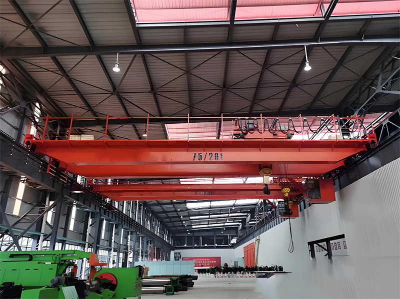
Lifting Height: Main hook: 16m, auxiliary hook: 18m.
II. Mechanism Calculation and Verification
Main Beam Strength and Stiffness Calculation
Load Combination: Includes deadweight (main beam + trolley), lifting load (75t), dynamic load coefficient (φ=1.1-1.3), and wind load (calculated based on P=127N/m²).
Bending Moment and Shear Force: Calculate the maximum mid-span bending moment and shear force at the supports using the simply supported beam model, and verify the bending and shear resistance of the main beam section.
Wheel Pressure Calculation: Considering the deadweight of the trolley (26t) and the full load (75t), calculate the maximum wheel pressure and verify the track bearing capacity.
Motor Power: Select the motor based on the running resistance (friction resistance + grade resistance) and speed (reference formula: P=F×v/η).
Trolley Mechanism Verification
Inertia and Wind Load: Calculate the impact of the trolley’s inertia (P = 167N) and wind load (P = 127N/m²) on the outriggers during starting and braking.
Stability Verification: The anti-overturning coefficient must meet ≥ 1.15 (refer to the calculation method for truck cranes).
III. Key Component Verification
Wire Rope Selection
The breaking strength of the main hook wire rope must meet a safety factor of ≥6 (calculated based on a lifting capacity of 75t + dynamic load factor).
Brake Selection
The braking torque of the hoisting mechanism brake must be ≥1.5 times the rated load torque.
End Beam Connecting Bolts
Verify the shear strength of the bolts, taking into account lateral loads (such as wind loads) and impact loads.
IV. Electrical and Safety Systems
Motor Capacity Verification
Motor power must be adjusted for high altitudes (>1000m) to account for temperature rise and heat dissipation.
Limits and Protective Devices
Install lifting height limits, overload protection, and trolley anti-collision devices.
V. Calculation Conclusion
Based on the above verification, the design of the QD75t×25m bridge crane meets the following standards:
GB/T 3811-2008 “Crane Design Code”.
GB 6067.1-2010 “Safety Regulations for Hoisting Machinery”.
Note: A complete calculation requires consideration of specific material parameters (such as the allowable stress of Q235B or Q345B steel), detailed load conditions, and detailed drawings. For additional information (such as finite element analysis or fatigue verification), please refer to the gantry crane truss design method.
Contact our crane specialists
Send us a message and we will get back to you as soon as possible.