Home → News → The Complete Guide to Selecting a 40T Double Girder Overhead Crane for Your Steel Mill
The Complete Guide to Selecting a 40T Double Girder Overhead Crane for Your Steel Mill
Selecting the right overhead crane is a critical capital investment decision for any steel mill. The wrong choice can lead to operational bottlenecks, increased downtime, and significant safety risks. A 40T double girder overhead crane is a common and vital workhorse in many steel production areas, from raw material handling to finishing bays. This guide outlines the key technical and operational factors to consider when specifying a 40T double girder overhead crane for a demanding steel mill environment.
1. Lifting Capacity & Duty Cycle: Beyond the Static 40T Mark
Specifying a 40T double girder overhead crane often begins with the nominal load rating. However, in the rigorous environment of a steel mill, this single figure is merely the starting point for a more critical engineering conversation. The true measure of a crane’s capability and longevity lies in its duty cycle – a classification that defines the intensity of its operational life.
Understanding Duty Class (FEM/ISO): The Crane’s “Athletic Profile” Think of duty class not as a weight limit, but as the crane’s built-in “constitution” for endurance. While a light-duty (A3) crane might handle 40T for a few cycles per hour, a steel mill’s continuous charging, transferring, and feeding operations demand a machine built for marathon performance. This is where Class A6 (Heavy Duty) and Class A7 (Severe Duty) become non-negotiable. These classifications mandate that every critical component—from the hoist motor’s insulation class and the gearbox’s design life, to the contactor’s electrical endurance and the structure’s fatigue resistance—is engineered for:
Frequent starts and stops: High inertia loads requiring robust thermal management in motors and drives.
Sustained operation: Capability to run for extended periods within an 8-12 hour shift.
High handling intensity: A significant portion of the working time is spent under load, not idle.
The Critical Factor: Actual Load Spectrum The most precise specification communicates not just “40 tons,” but how that capacity is used. A crane that consistently handles loads near its 40T capacity experiences far greater stress than one primarily moving 15-20T loads, even if both are rated for 40T. When defining your needs, consider:
Average operating load: The typical weight lifted during most cycles.
Maximum load frequency: How often the crane will lift at or near its 40T capacity.
Lifting height and travel distance per cycle: These determine the duration and energy expenditure of each operation.
Engineering Implications: Why It Matters Selecting an under-classified crane for a severe steel mill duty is a high-risk decision that leads to:
Increased safety risk: Components operating beyond their designed stress limits.
Excessive downtime and maintenance costs: The opposite of the reliability a steel mill requires.
Conversely, a properly classed 40T double girder overhead crane—designed from the ground up for A6/A7 duty—embodies built-in resilience. It features components with higher safety margins, superior cooling, and materials selected for durability under cyclic stress. This results in predictable maintenance intervals, longer service life, and ultimately, a lower total cost of ownership.
Recommendation for Specification: When discussing your 40T double girder overhead crane project, move beyond the basic capacity. Provide your potential supplier with detailed operational data or process descriptions to allow them to recommend the correct duty class. A reputable manufacturer will proactively ask for this information, ensuring the proposed design is not just adequate, but optimally engineered for your specific operational rhythm and long-term reliability.
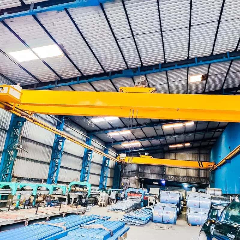
2. Span & Workshop Layout Integration: The Foundation of Efficient Workflow
The span of a 40T double girder overhead crane—the distance between the centerlines of its parallel runway rails—is far more than a dimensional footnote. It is a fundamental design parameter that dictates the crane’s coverage, influences its structural integrity, and ultimately determines how seamlessly it integrates into your steel mill’s material flow. Correctly specifying and engineering the span is critical to unlocking the crane’s full productive potential and avoiding costly operational constraints.
Precision Definition: Beyond a Simple Measurement Accurate span determination requires a meticulous, on-site approach. It is not merely the width of the building but the clear, unobstructed distance between the runway rails, accounting for:
Runway Rail Centerlines: The definitive reference points for span measurement.
Column & Obstruction Clearance: Ensuring the crane bridge and its protruding components (cabin, cable reels, conduits) safely clear all building columns, piping, ventilation ducts, and other fixed structures.
End Approach: The critical distance the hook can travel horizontally, from the centerline of the runway rail towards the building wall. Maximizing end approach is essential for servicing all floor areas and minimizing “dead zones.”
The Interplay of Span, Structure, and Performance For a 40T double girder overhead crane, the span has a direct and exponential impact on its engineering:
Bridge Girder Design & Deflection: As span increases, the bridge girders must be strengthened to support the 40T load plus their own weight with minimal deflection. Excessive vertical deflection (sag) can affect hoisting height and precise positioning. A well-designed double girder overhead crane for steel mills prioritizes high structural rigidity, often requiring optimized girder profiles (box-type or truss-style) to meet strict deflection limits (typically L/800 to L/1000) under full load.
End Truck & Wheel Load: The span directly affects the load borne by each end truck and its wheels. Longer spans increase the bridge’s self-weight, resulting in higher wheel loads on the runway rails and, consequently, on the supporting building columns or girders. A professional assessment must verify that the existing runway support structure can handle these dynamic loads, or plan for necessary reinforcements.
Lateral Forces & Crab Alignment: The long travel drives must provide sufficient torque to accelerate and decelerate the entire bridge structure across the span, especially in high-duty cycles. Proper alignment of the end trucks and synchronization of their drives are crucial to prevent diagonal travel (“crabbing”), which causes excessive wear on rails and wheels.
Integration with Steel Mill Processes: A Systems View The crane must be an integral component of the workshop’s workflow, not an isolated piece of equipment. Integration requires analysis of:
Material Flow Paths: Mapping the most frequent load travel routes (e.g., from scrap bay to furnace, from casting to cooling beds) to ensure the crane’s coverage is optimal.
Interaction with Other Equipment: Defining clearances with ladle turrets, charging machines, transfer cars, and other cranes (through interlocks or zone control systems) is vital for safe, interference-free operation.
Future-Proofing: Considering potential changes in plant layout, new production lines, or increased capacity. Discussions may include provisions for future span extension (if structurally reserved) or increased duty requirements.
Consequences of Inadequate Planning Underestimating the importance of precise span integration leads to:
Reduced Utility: Inaccessible floor areas creating workflow bottlenecks.
Accelerated Wear: Misalignment and crabbing leading to premature failure of wheels and rails.
Structural Risk: Overloading of runway supports not designed for the calculated wheel loads.
Safety Hazards: Inadequate clearances increasing the risk of collisions.
Recommendation for Specification: Treat span determination as a collaborative, front-end engineering exercise. Engage with your crane provider to conduct a detailed site survey. Provide them with detailed workshop layout drawings, including all obstructions and intended material flow patterns. A reputable manufacturer will use this data not only to quote a span, but to perform essential structural calculations for wheel loads, girder deflection, and drive power requirements, ensuring your 40T double girder overhead crane is a perfectly fitted, reliable, and enduring cornerstone of your steelmaking operation.
3. Environmental Resilience: Engineering for the Crucible
In a steel mill, the operating environment is not a background condition—it is an active, aggressive adversary. For a 40T double girder overhead crane, specifying standard industrial-grade components is a guarantee of premature failure. True reliability is engineered through a proactive defense against a triad of relentless challenges: extreme heat, pervasive particulate matter, and mechanical shock. Environmental resilience, therefore, moves from a desirable feature to the foundational design philosophy.
1. The First Front: Extreme Thermal Loads Prolonged exposure to radiant and convective heat from furnaces, ladles, and hot product fundamentally alters material properties and component life.
Critical Component Protection: Electric motors and gearboxes serving areas with ambient temperatures consistently above 40°C (104°F) require designated Class H (180°C) or higher insulation systems. Hoist machinery may be housed in insulated enclosures or equipped with heat-reflective shields.
Structural Considerations: Steel strength decreases as temperature rises. In high-heat zones (e.g., near casting), the structural design of the double girder overhead crane bridge may incorporate derating factors or utilize materials with better high-temperature performance for critical connections.
Lubrication System Integrity: Standard greases and oils degrade rapidly. High-temperature, synthetic lubricants with superior oxidation stability are specified for all bearings, gears, and open gear sets on the runway.
Electrical & Control Systems: Wiring must employ high-temperature, ceramic-coated cables (e.g., SILICONE or FEP insulation). Cable reels and festooning systems must be rated for thermal durability. PLCs and drives are housed in ventilated or air-conditioned cabinets.
2. The Second Front: Abrasive Dust and Particulate Infiltration Metallic dust, mill scale, and general grime are more than a nuisance; they are a potent abrasive and conductive contaminant.
Sealed for Life: Gearboxes are fully enclosed with labyrinth seals. Hoist and travel motors should meet a minimum of IP55 (dust-protected and water-jet resistant), with IP65 being preferable for critical components.
Electrical Enclosure Integrity: All control panels, junction boxes, and resistor banks must achieve a high IP rating to prevent conductive dust from causing short circuits, tracking, and insulation failure.
Mechanical Wear Mitigation: Wheel flanges, rail surfaces, and open gear drives are subject to accelerated wear. Premium-grade wheel materials (e.g., forged alloy steel) with hardened treads, and optional automatic lubrication systems for rails and gears, are essential to maintain alignment and reduce maintenance intervals.
3. The Third Front: Humidity, Corrosion, and Physical Shock The atmosphere may contain corrosive agents, while the nature of handling heavy, swinging loads imposes dynamic stresses.
Corrosion Defense: A multi-stage coating system—comprising blast cleaning (Sa 2.5), a high-build epoxy primer, and a chemical-resistant polyurethane topcoat—is standard. For highly corrosive areas, components may be hot-dip galvanized.
Robust Construction for Dynamic Loads: The 40T double girder overhead crane structure is designed for Group 4 (A7/D8) load classification, accounting for not just the static weight but also the dynamic forces from hoisting, traversing, and potential side pulls. All connections utilize high-strength bolts.
Shock-Resistant Electronics: Critical sensors (limit switches, load cells) and electrical components are selected or housed to withstand vibration and incidental impact.
The Systemic Approach: More than a Sum of Parts True environmental resilience is not achieved by simply upgrading individual parts. It requires a systems-engineering approach where all protective measures are integrated. For instance, a sealed, high-IP motor (for dust) must also have Class H insulation (for heat). An air-conditioned cabin protects the operator and electronics, but its filters must handle the specific particulate load of the workshop.
Recommendation for Specification: Define the environment with forensic detail. Provide your crane manufacturer with a zone map of your workshop, indicating ambient temperature ranges, proximity to heat sources, dust concentration levels, and any presence of water or chemicals. This allows for a graded specification, where components in the most severe zones receive the highest level of protection, optimizing capital expenditure. The specification for your 40T double girder overhead crane should explicitly list the required standards (e.g., IP ratings, insulation classes, paint system) for each major subsystem, ensuring the delivered machine is not just rated for 40 tons, but is fortified for the furnace.
4. Hoisting Mechanism & Control Systems: The Nexus of Precision, Power, and Reliability
The hoisting mechanism of a 40T double girder overhead crane is its primary functional system, responsible for the fundamental act of lifting and lowering. In a steel mill, this is not a simple vertical movement but a critical process step requiring immense power, precise control, and unwavering reliability under punishing conditions. The integration of this mechanism with advanced control systems transforms a robust machine into an intelligent, responsive production tool.
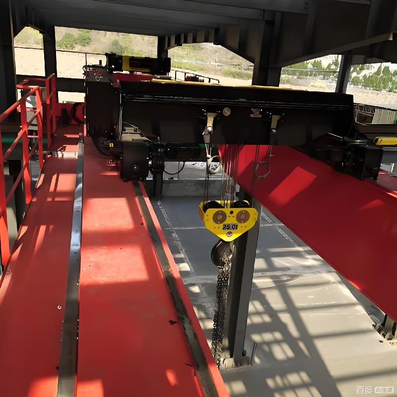
1. The Hoisting Mechanism: Engineered for Severe Duty The core hoist assembly on a mill-duty double girder overhead crane is a self-contained unit built to exceed the nominal 40-ton rating under dynamic, high-cycle conditions.
Drum and Rope System: The wire rope drum is designed with precise grooving and sufficient rope capacity for the full lift height, often with multiple layers. The rope itself is a critical wear item; for 40T applications, a high-grade, rotation-resistant, steel-cored wire rope with appropriate flexibility and abrasion resistance is specified. Regular inspection and replacement protocols are essential.
Hook Block Assembly: The 40T hook block is a forged or laminated component, equipped with a heavy-duty swivel bearing and safety latch. It is designed with a high factor of safety, typically complying with FEM or DIN standards for Group M8 (heavy-duty) classification.
Gearbox and Braking: The reduction gearbox is a precision component, sized for A6/A7 duty with ample service factor to handle the high inertial loads of frequent starts and stops. Dual braking is mandatory: a primary, electrically released disc or caliper brake on the high-speed shaft, and a secondary, mechanically engaged fail-safe brake (often on the low-speed shaft) that activates automatically in the event of power loss or primary brake failure.
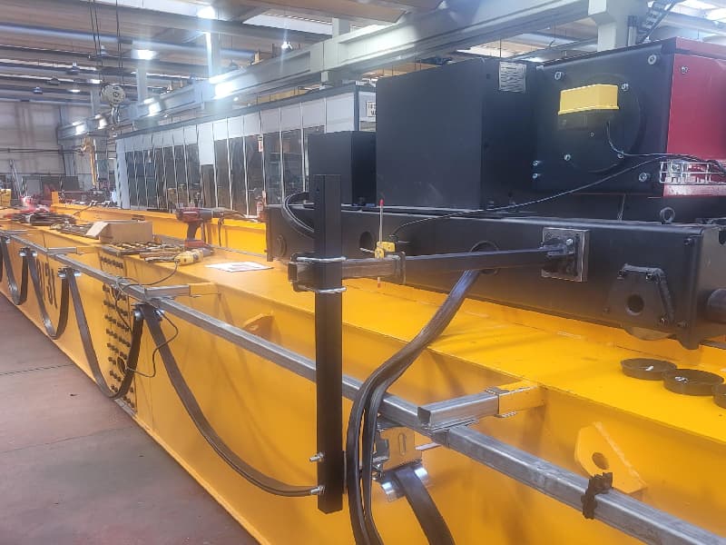
2. Drive Technology: From Basic Performance to Premium Control The choice of drive system dictates the crane’s performance characteristics, energy efficiency, and impact on the load and structure.
Conventional AC Squirrel-Cage Drives: A robust and cost-effective solution for applications where precise speed control is not critical. However, they offer limited control over acceleration and deceleration, leading to higher mechanical shock.
Variable Frequency Drive (VFD) / AC Vector Control: This is the industry-preferred standard for a modern 40T double girder overhead crane in a steel mill. VFDs provide:
Precision Control: Infinitely variable speed for both hoisting and traversing motions, enabling smooth, inch-perfect load positioning—critical for ladle pouring or aligning heavy slabs.
Soft Start/Stop: Dramatically reduces mechanical stress on gears, brakes, and the entire structure by controlling ramp-up and ramp-down currents.
Enhanced Safety: Features like torque verification and controlled descent prevent uncontrolled load lowering.
Energy Efficiency: Significantly reduces inrush current and overall power consumption compared to direct-on-line starters.
3. Control Interface: Matching Operator to Task The human-machine interface must be intuitive, reliable, and safe for the operational context.
Pendant Control: A robust, hanging station offering direct tactile control. Suitable for areas where the operator can safely walk alongside the load.
Radio Remote Control: Increasingly essential for steel mills, it provides unparalleled operator mobility and safety. The operator can position themselves for the best view, away from heat, dust, or potential load swing paths. Systems must offer secure, anti-interference frequency hopping technology and ergonomic, mill-duty handsets.
Enclosed Operator’s Cab: Provides a protected environment with panoramic visibility, essential for complex, long-distance maneuvers or in areas with excessive ambient noise. Cabs should be air-conditioned, insulated, and mounted to minimize vibration.
4. Advanced Functionality for Operational Excellence Beyond basic lift-and-carry, modern control systems enable transformative features:
Anti-Sway Technology: An intelligent software function integrated with the trolley and bridge VFDs. It automatically calculates and applies control commands to minimize load swing induced by acceleration/deceleration, drastically reducing positioning time and enhancing safety, particularly for large-dimension loads like coils or plates.
Load Positioning & Autopilot: Programmable logic allows for the setting of pre-defined lift heights or trolley/bridge positions, automating repetitive moves and improving cycle time consistency.
Condition Monitoring: Sensors can monitor key parameters (motor temperature, brake wear, cycles count) and feed data to a diagnostic system for predictive maintenance planning.
Recommendation for Specification: When specifying the hoist and control systems for your 40T double girder overhead crane, define the required performance envelope: needed lifting speeds for productivity, precise positioning tolerances, and the desired level of automation. Explicitly demand VFD control on all motions as a baseline for a modern, efficient, and protective installation. Discuss the operational workflow to select the optimal control interface (radio remote is strongly recommended for most steel mill applications). Finally, inquire about available advanced software packages (like anti-sway) that can deliver a rapid return on investment through significantly improved operational efficiency and safety. The goal is to procure not just a hoist, but a precision lifting system.
5. Safety & Redundancy: Designing for Zero-Failure Tolerance
In the unforgiving environment of a steel mill, where a 40-ton load may be molten metal or a critical structural component, safety transcends regulatory compliance—it becomes the foundational pillar of operational integrity. For a 40T double girder overhead crane, safety is not a collection of add-on devices but a holistic, embedded design philosophy. This philosophy is built on two interdependent principles: intrinsic protection through engineered safeguards and operational assurance through system redundancy. The goal is to create a system where no single point of failure can lead to a catastrophic event.
1. Intrinsic Safety: The Non-Negotiable Core Protections These are the mandatory, independently functioning devices that form the first and most critical defense layer. Their selection and installation must comply with the highest international standards (such as ISO 23853, FEM, or CMAA Spec 70/80 for mill-duty cranes).
Overload Limiting Device: A mandatory sensor, typically a strain-gauge type, installed in the load path (on the sheave pin or the rope anchorage). It continuously monitors the actual load and is set to trigger an alarm (at ~90% of SWL) and a complete cut-off of hoisting motion (at ~105-110% of SWL). In a steel mill, this device must be exceptionally robust to withstand shock loads and thermal variations without losing calibration.
Fail-Safe Braking System: As detailed in the hoisting mechanism, a dual, redundant braking system is essential. The primary service brake and the secondary holding brake must be physically and electrically independent, ensuring controlled stopping and positive load holding even in a power loss scenario.
Travel Limit & Anti-Collision Systems:
End-of-Travel Limit Switches: Robust, mechanically activated switches at the extremes of bridge and trolley travel to prevent overrun and collision with the runway ends or other structures.
Zone Control & Anti-Collision: For workshops with multiple cranes operating on parallel or intersecting runways, radar or encoder-based systems are used to enforce minimum separation distances, automatically slowing or stopping cranes to prevent collisions.
Emergency Stop Circuitry: A dedicated, hardwired safety circuit (Category 0 stop), with prominently marked E-Stop buttons on all control stations (pendant, cab, radio remote) and at key locations on the crane, allowing for immediate power cutoff to all crane motions from multiple points.
2. Redundancy & Fault Tolerance: Engineering for Continuity Beyond preventing failure, the design must ensure that if a non-critical component does fail, the system can either continue safe operation or execute a controlled, safe shutdown. This is the essence of redundancy for a double girder overhead crane in a 24/7 production environment.
Drive System Redundancy: In critical applications, dual-motor hoist drives with independent gear trains provide a level of continued, albeit reduced-capacity, operation if one motor or drive fails.
Power Supply Redundancy: For cranes serving absolutely critical processes, a dual or backup power feed system can be specified to ensure operation in case of a main power line failure.
Control System Architecture: The Programmable Logic Controller (PLC) and safety relay systems should be designed with watchdog timers and self-diagnostic routines. Critical safety functions (like the overload limit circuit) often bypass the main PLC entirely, operating through a dedicated, certified safety relay (e.g., SIL-2 rated) for guaranteed response.
Structural Redundancy: The double girder design itself offers inherent structural redundancy compared to a single girder. The load path is distributed across two primary girders and two end trucks, providing a safer margin in the unlikely event of localized damage.
3. Environmental Hardening of Safety Devices All safety components must be specified to survive the mill environment. This includes:
High-Temperature Rated Sensors: Limit switches and proximity sensors near heat sources must have high-temperature bodies and seals.
Dust and Water Protection: All safety devices should have a minimum IP65 rating to prevent ingress of conductive dust and moisture, which could cause false triggers or failures.
Mechanical Ruggedness: Components must withstand vibration, shock, and incidental contact.
4. The Human Factor: Interfaces for Safe Operation The safety system must actively support the operator.
Clear, Redundant Indication: Visual (beacon lights) and audible alarms for overload, approach to limits, and system faults.
Ergonomic and Fail-Safe Controls: Control levers that return to neutral on release, dead-man switches on radio remotes, and interlocks that prevent unsafe operation sequences.
Comprehensive Documentation & Training: Detailed, mill-specific safety procedures and regular operator training are the final, crucial layer in the safety ecosystem.
Recommendation for Specification: When defining safety requirements, move beyond a checklist. Demand a Safety Requirement Specification (SRS) from your crane provider, which documents the safety functions, their Performance Levels (PL) or Safety Integrity Levels (SIL), and the validation methods. Explicitly require that all safety-critical components are from reputable manufacturers with proven mill-duty pedigrees. For your 40T double girder overhead crane, insist on a demonstration and validation of all safety functions during Factory Acceptance Testing (FAT). The specification should treat safety not as a cost item, but as the core value proposition, ensuring the crane is an asset you can trust implicitly at the heart of your demanding operation.
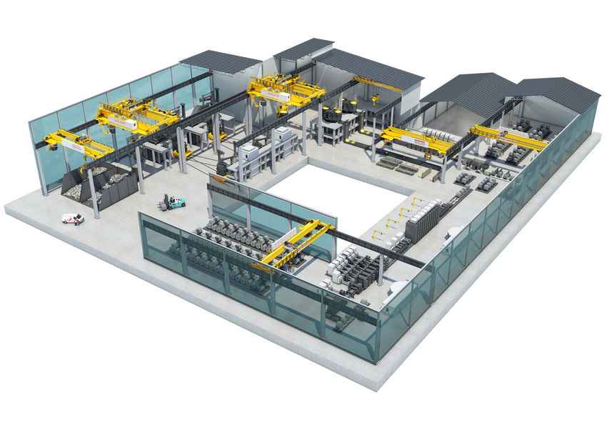
6. Installation, Commissioning & Lifecycle Support: Transforming Capital Investment into Operational Asset
The final phase of acquiring a 40T double girder overhead crane—encompassing its installation, commissioning, and long-term support—is where engineering design and manufacturing quality are validated in the field. This phase is not a mere appendage to the purchase but the critical process that determines whether the crane will become a reliable, high-performing asset or a source of persistent operational disruption. For a steel mill, where downtime is measured in lost production and significant revenue, a professional, systematic approach to this phase is paramount.
1. Professional Installation: The Foundation of Long-Term Reliability A perfectly manufactured crane can be rendered unreliable by poor installation. This stage requires precision, planning, and specialized expertise.
Pre-Installation Site Audit & Runway Certification: A professional supplier conducts a thorough survey of the existing runway system before installation. This includes:
Dimensional & Alignment Verification: Using laser surveying tools to check runway gauge, span, straightness, and elevation (camber). Misalignment is a primary cause of wheel flange wear and “crabbing.”
Structural Integrity Assessment: Verifying that the supporting columns, girders, and rail fastenings can handle the dynamic wheel loads of the new 40T double girder overhead crane, as per the initial design calculations. Reinforcement recommendations are provided if needed.
Turnkey Project Management: A dedicated site manager oversees the entire process: receiving and inspecting components, coordinating heavy lift equipment, managing on-site trades, and ensuring strict adherence to safety protocols (e.g., Lockout-Tagout, Permits to Work). This single point of accountability is crucial for complex installations in active steel plants.
Precision Assembly & Alignment: Critical steps include the calibrated alignment of bridge girders on the end trucks, precise leveling of the crane bridge on the runways, and correct tensioning of all mechanical and electrical connections. These procedures follow detailed, manufacturer-approved methodologies.
2. Systematic Commissioning & Performance Validation: From Static to Dynamic Asset Commissioning is the structured process of testing, adjusting, and documenting every function of the crane to meet its design specifications. It is the formal handover from installer to operator.
Phased Testing Protocol:
Static Checks: Verification of all bolt torques, electrical connections, safety device installations, and insulation resistance.
No-Load Functional Tests: Operating all motions (hoist, trolley, bridge) without load to verify direction, limit switch functionality, brake operation, and control responsiveness.
Load Testing: The definitive performance validation. This involves incremental load tests up to 110% of the SWL (40T), as per international standards (e.g., ISO 4310). The test measures and documents critical parameters: brake performance (hold and stopping distance), structural deflection, motor current draw, and functionality of the overload limiter at its set points.
System Integration & Fine-Tuning: This includes calibrating Variable Frequency Drive (VFD) parameters for optimal acceleration/deceleration ramps, setting precise stopping positions, and testing advanced functions like anti-sway control with actual loads to ensure they meet the mill’s operational needs.
Comprehensive Documentation Handover: The delivery is not complete without a full dossier, including:
As-Built Drawings and Wiring Diagrams.
Certified Load Test Report.
Complete Operations & Maintenance (O&M) Manuals, with lubrication charts, parts lists, and troubleshooting guides.
Safety Logbook and Conformity Documentation (CE, ISO, etc., as applicable).
3. Lifecycle Support: A Strategic Partnership for Total Cost of Ownership The relationship with the supplier should transform post-commissioning into a long-term technical partnership aimed at maximizing uptime and optimizing the total cost of ownership over the crane’s 20-30 year life.
Proactive & Predictive Maintenance Programs: Moving beyond reactive repairs. These can include:
Scheduled Inspections: Regular visits by factory-trained technicians to inspect critical components (brakes, wire ropes, electrical contacts, structural integrity).
Condition Monitoring: Utilizing vibration analysis, thermal imaging, and oil analysis to detect early signs of gearbox, motor, or bearing wear before failure occurs.
Technical Support & Spare Parts Ecosystem: Guaranteed access to:
Expert Hotline: Direct access to application engineers for troubleshooting.
Genuine, Long-Lead Spare Parts Inventory: Assurance that critical, mill-duty specific components (special motor windings, gear sets, proprietary brake linings) are available when needed, minimizing downtime.
Modernization & Retrofit Services: As technology evolves, the ability to upgrade control systems, drives, or safety devices on the existing crane structure to extend its service life and enhance performance.
Operator & Maintenance Training: Conducting certified training sessions for the mill’s staff is an investment in safety and reliability. Trained personnel perform better daily inspections, recognize early warning signs, and conduct routine maintenance correctly.
Recommendation for Specification: In procurement contracts, explicitly define the scope and standards for installation, commissioning, and support. Require a detailed Project Execution Plan and Commissioning Protocol from the supplier prior to order. Prioritize suppliers who offer not just a crane, but a Lifecycle Service Agreement—a contract that aligns their incentives with your operational uptime and long-term cost control. For your 40T double girder overhead crane, the true value is realized not upon delivery, but upon seamless integration into your production flow and its sustained, reliable performance over decades. This final phase ensures the transition from a capital expense to a fully capitalized, productive asset.
Conclusion: A Strategic Asset, Not Just a Purchase
Specifying a 40T double girder overhead crane for your steel mill workshop is a complex process that balances engineering, operational needs, and total lifecycle cost. By meticulously evaluating these factors—duty class, environmental hardening, control precision, and safety systems—you move beyond a simple equipment purchase to acquiring a strategic, reliable, and productive asset.
The most successful projects partner with crane manufacturers who understand the profound challenges of the steel industry and can translate those needs into a robust, customized 40T double girder overhead crane solution built for performance, safety, and longevity.