HomeNews → Structural design of a 50/10T double-girder bridge crane with a span of 28m

Structural design of a 50/10T double-girder bridge crane with a span of 28m

Design Overview

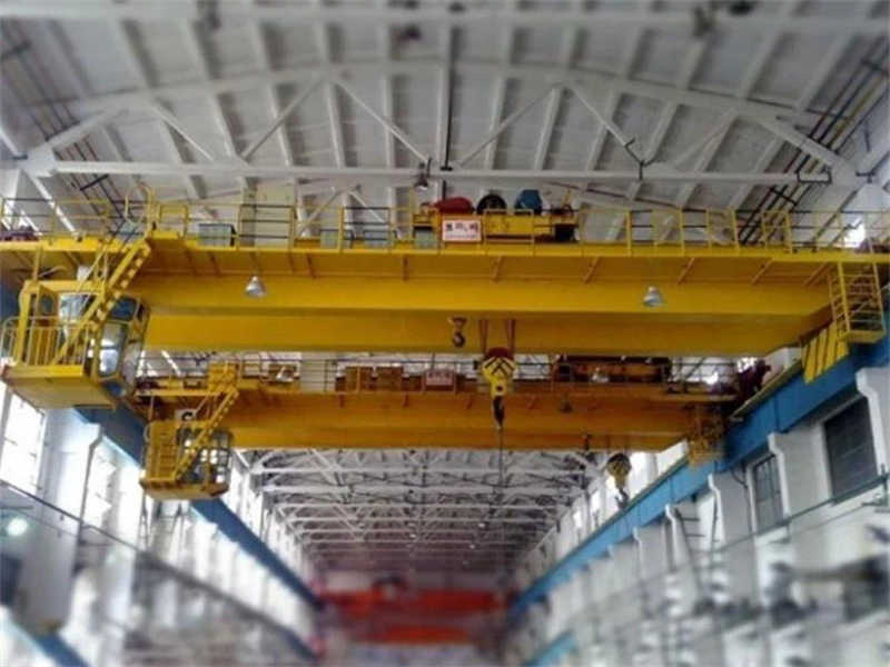
This design proposal addresses the metal structure design of a 50/10T (50-ton main hook, 10-ton auxiliary hook) double-girder overhead crane with a span of 28m. This crane utilizes a mid-rail box-type double-girder structure with an A6 service class, suitable for heavy-load lifting operations in general industrial environments. The design utilizes the allowable stress method and computer-aided design (CAD) to ensure that the structure meets national standards for strength, stiffness, stability, and fatigue life.

Key Design Features:

  • The box-type double-girder structure provides excellent bending and torsional resistance.
  • The main and end beams are connected using high-strength bolts for easy transportation and installation.
  • The mid-rail layout optimizes trolley stability.
  • The main and auxiliary hoist mechanisms are independently designed to meet diverse lifting requirements.
qd type 50/10 ton hook bridge crane

Design Parameters and Technical Requirements

Basic Parameters

Based on the design requirements and relevant standards, the crane’s main technical parameters are as follows:

Table 1: Main design parameters of crane

Parameter CategoryMain lifting mechanismAuxiliary lifting mechanismTrolley operating mechanismTrolley running mechanism
Rated lifting capacity (t)5010
Lifting height (m)1218
Lifting speed (m/min)12.1/1.21(Dual speed)10.3
Working LevelM6M5M6M6
Running speed(m/min)75-90(Adjustable)35-45(Adjustable)
Track gauge/wheelbase(m)28(Span)2.5(Trolley gauge)
Wheelbase(m)3.75

Working Environment

  • Indoor installation, ambient temperature -20°C to +45°C
  • Maximum relative humidity ≤ 95%
  • Altitude ≤ 1000m
  • Non-explosive hazardous environment, no corrosive media
  • Power supply: Three-phase AC 380V, 50Hz

Design Standards and Specifications

The design complies with the following national standards and industry specifications:

  • GB/T 3811-2008 “Crane Design Code”
  • GB 6067.1-2010 “Safety Regulations for Hoisting Machinery”
  • GB/T 14405-2011 “General-purpose Bridge Cranes”
  • JB/T 3695-2008 “Electric Hoist Bridge Cranes”
  • FEM 1.001-1998 “Crane Design Code”

Metal Structure Design

Bridge Structure Design

The bridge is the core component of a double-girder bridge crane, consisting of two main beams, two end beams, and auxiliary components such as walkways and guardrails. This design utilizes a center-gauge box-type double-girder structure, which offers advantages such as high rigidity, light weight, and mature manufacturing technology.

Main Girder Design:

  • Cross-Section: Off-track box girder (center-gauge)
  • Main Girder Height: Based on the empirical formula H = (1/14 to 1/18) L, H = 1.8m is used.
  • Main Girder Width: B = (1/50 to 1/60) L, B = 0.6m is used.
  • Upper Flange Plate Thickness: δ₁ = 20mm (Q345B)
  • Lower Flange Plate Thickness: δ₂ = 18mm (Q345B)
  • Web Plate Thickness: δ₃ = 8mm (Q235B)
  • Stiffeners Rib Arrangement: Transverse stiffeners are spaced 1.5m apart, and longitudinal stiffeners are arranged continuously.

End Beam Design:

  • Cross-section: Box-type
  • Height: 0.8m
  • Width: 0.5m
  • Material: Q345B welded steel plate
  • Connected to the main beam using high-strength bolts (10.9-grade M24).

Main Beam Camber Design:

To compensate for downward deflection under load, the main beam has a preset camber value of 1/1000 of the span (L), or 28mm. The camber curve adopts a quadratic parabola distribution.

Load Calculation and Combination

According to GB/T 3811, crane structural design must consider the following loads:

Main loads:

  1. Deadweight load (P_G): includes the weight of the bridge, hoisting mechanism, operating mechanism, and electrical equipment.
    • Estimated main beam deadweight: approximately 8.5t per beam.
    • End beam deadweight: approximately 3.2t per beam.
    • Trolley deadweight: approximately 12t (including lifting gear).
  2. Lifting load (P_Q): Rated lifting capacity 50t, considering a dynamic load factor of φ₂ = 1.15.
    • Calculated load: P_Q = 50 × 1.15 =57.5t

Additional Loads:

  • Horizontal Inertia Load (P_H): Considered at 10% of the vertical load
  • Wind Load (P_W): Not considered for indoor operations
  • Temperature Load: Not considered for indoor operations

Load Combinations:

Combinations based on the ultimate load capacity limit state:

  • Combination I: 1.2P_G + 1.4P_Q (primary load combination)
  • Combination II: 1.2P_G + 1.4P_Q + 1.1P_H (primary load + horizontal inertia load)

Strength and Stiffness Calculation

Main Beam Strength Verification:

Calculate the maximum mid-span bending moment using the simply supported beam model:

Mmax = (qL²)/8 + (PL)/4

Calculation Results:

  • Maximum Bending Stress: σ_max = 185 MPa < [σ] = 210 MPa (Q345B)
  • Maximum Shear Stress: τ_max = 95 MPa < [τ] = 120 MPa
  • Local Compressive Stress: σ_c = 135 MPa < [σ_c] = 315 MPa

Main Beam Stiffness Verification:

Under rated load, the static deflection of the main beam at mid-span must meet the following requirements:

f ≤ L/800 = 35 mm

Stability Verification:

  • For box beams, the overall stability coefficient φ_b = 1.0 > 0.95; local stability considerations are necessary.
  • Local stability of the web and flange plates is ensured by installing transverse and longitudinal stiffeners.

Fatigue Strength Calculation

Based on duty level A6 (M6), fatigue verification is performed based on 2×10^6 cycles:

  • Stress amplitude Δσ = σ_max – σ_min = 125 MPa
  • Allowable stress amplitude [Δσ] = 160 MPa (Detail Category W2)
  • Fatigue strength is considered acceptable if Δσ ≤ [Δσ] is met.

Mechanism design

Main lifting mechanism design

Main lifting mechanism working level M6, adopting dual speed control (12.1/1.21m/min):

Main component selection:

  • Motor: YZR315M-8, 90kW, JC40%, 715r/min
  • Wire rope: 6W(19)+IWR-24-170, breaking tension ≥380kN
  • Pulley block: 6 times, diameter φ600mm
  • Drum: diameter φ880mm, length 2200mm, material HT200
  • Reducer: ZQ1000-50-3CA, speed ratio 50
  • Brake: YWZ5-315/50, braking torque 1600N·m

Safety device:

  • Overload limiter: set to alarm at 110% of rated load and cut off lifting power at 125%
  • Height limiter: double protection (hammer type and spiral type)
  • Overspeed protection: used for fast gear

Auxiliary hoisting mechanism design

Auxiliary hoisting mechanism working level M5, rated lifting capacity 10t:

Main parameters:

  • Lifting speed: 10.3m/min
  • Lifting height: 18m
  • Motor: YZR225M-6, 30kW, JC40%, 960r/min
  • Wire rope: 6W(19)+IWR-16-170
  • Reducer: ZQ650-31.5-3CA
  • Brake: YWZ3-250/45

Trolley travel mechanism

Trolley running mechanism adopts four-corner drive Drive mode ensures synchronization:

Main Parameters:

  • Operating speed: 75-90 m/min (variable frequency speed regulation)
  • Drive motor: YZR160L-6, 11kW x 4
  • Reducer: ZSC600-VI-1
  • Wheel diameter: φ600mm, material: ZG340-640
  • Track model: QU70

Design Features:

  • VFD control ensures smooth starting and braking
  • Buffers and limit switches at both ends
  • Drive pulley ratio: 1/2 (8 total wheels, 4 drive wheels)

Trolley Mechanism

The trolley mechanism utilizes a centralized drive system.

Main Parameters:

  • Operating Speed: 35-45 m/min (Variable Frequency Drive)
  • Drive Motor: YZR132M2-6, 4.5 kW
  • Reducer: ZSC400-VI-2
  • Wheel Diameter: φ320 mm, Material: ZG340-640
  • Track Model: P38

Safety Devices:

  • Buffers: Two rubber buffers at each end
  • Limit Switches: Dual protection at end of travel
  • Anti-derailment Device: Angular stop

Electrical Control System Design

Power Supply and Distribution System

  • Main Power Supply: AC 380V, 50Hz, three-phase, five-wire
  • Power Supply: Safety busbar (main busbar)
  • Trolley Power Supply: Auxiliary busbar (flat cable backup)
  • Main Power Supply Protection: Short circuit, overcurrent, undervoltage, and zero position protection

Drive Control Method

  • Main Hoist: Rotor series resistor speed control + eddy current braking (dual-speed control)
  • Auxiliary Hoist: Rotor series resistor speed control
  • Trolley/Trolley: Variable Frequency Drive (VVVF) speed control, starting acceleration 0.5m/s²

Operation Method

  • Ground-based wired remote control (IP65 protection rating)
  • Operation from the driver’s cab (optional), compliant with ISO standards
  • Control Voltage: AC 220V (power), DC 24V (control signal)

Safety Protection Devices

  1. Electrical Protection:
    • Overcurrent Protection
    • Short Circuit Protection
    • Phase Loss Protection
    • Emergency Stop Button
  2. Mechanical Protection:
    • Capacity Limiter
    • Height Limiter (Independent for Main and Auxiliary Hooks)
    • Travel Limiter (Trolley and Carriage)
    • Interlock Protection (Door Limit, Railing Switch)
  3. Status Monitoring:
    • Motor Temperature Monitoring
    • Brake Wear Monitoring
    • Wire Rope Slack Detection

Manufacturing and Installation Requirements

Material Selection

  • Main Beam and End Beam: Q345B low-alloy high-strength steel
  • Trolley Frame: Q235B carbon structural steel
  • Roller: HT200 gray cast iron or Q235B steel plate
  • Wheels: ZG340-640 cast steel, tread hardened to HB300-380

Welding Procedure Requirements

  • Main Welds: Submerged arc automatic welding, 100% ultrasonic testing
  • Fillet Welds: CO₂ gas shielded welding, weld leg size not less than 0.7 times the plate thickness
  • Post-weld Treatment: Overall annealing for stress relief
  • Welding Standard: Comply with GB/T 12467.3-2009

Machining Accuracy Requirements

  1. Main Beam:
    • Camber (28 ± 3) mm
    • Sidebow ≤ L/2000 = 14 mm
    • Web Flatness ≤ 3 mm/m²
    • Flange Tilt ≤ b/200 = 3 mm
  2. Wheels:
    • Diameter Tolerance IT9
    • Tread Hardness HB300-380
    • Diameter Difference Between Wheels on the Same Track Surface ≤ 0.1%

Installation and Commissioning

  1. Installation Sequence:
    • End Beam Assembly → Main Beam Hoisting → High-Strength Bolt Connection → Trolley Installation → Electrical Equipment Installation → Accessory Installation
  2. Commissioning Details:
    • No-Load Test: Operate each mechanism for 2 hours to inspect for abnormal vibration and noise.
    • Static Load Test: 1.25 times the rated load to inspect structural deformation and welds.
    • Dynamic Load Test: 1.1 times the rated load to verify the performance of each mechanism.
    • Safety Device Test: Verify all limit and protective functions.

Calculations and Drawings

Main Calculation Contents

  1. Main Beam Strength, Stiffness, and Stability Calculations
  2. End Beam Connection Calculations (Shear Capacity of High-Strength Bolts)
  3. Hoisting Mechanism Calculations (Wire Rope, Drum, and Motor Selection)
  4. Traveling Mechanism Calculations (Wheel Pressure, Slip Verification, and Motor Power)
  5. Overturning Stability Calculations (Various Operating Conditions)

Drawing List

  1. General Assembly Drawing (A0 Size): QZ50-28-00
  2. Main Beam Component Drawing (A1 Size): QZ50-28-01
  3. End Beam Component Drawing (A1 Size): QZ50-28-02
  4. Trolley Assembly Drawing (A1 Size): QZ50-28-03
  5. Main Hoisting Mechanism Drawing (A1 Size): QZ50-28-04
  6. Auxiliary Hoisting Mechanism Drawing (A2 Size): QZ50-28-05
  7. Electrical Schematic Diagram (A1 Size): QZ50-28-06

Economic and safety analysis

Material cost estimation

Table 2: Main material usage and cost estimates

Material nameSpecificationsQuantityUnitUnit price (yuan)Total (10,000 yuan)
Q345B steel plateδ=8-20mm42t650027.3
Q335B steel plateδ=6-16mm18t52009.36
SteelVarious specifications8t60004.8
Wire rope6W(19)600m352.1
Electrical components12.5
Total56.06

Safety and Reliability Measures

  1. Structural Safety:
    • Box-type main beam for excellent torsional resistance
    • 100% nondestructive testing of critical welds
    • Safety factors meet GB3811 requirements
  2. Mechanical Safety:
    • Dual braking system (electrical + mechanical)
    • Wire rope safety factor n ≥ 6 (main hoist)
    • Anti-derailment device (trolley and carriage)
  3. Operational Safety:
    • Comprehensive safety protection system
    • Clear load markings and operating instructions
    • Recommended regular inspection system (daily, monthly, and annual inspections)

Maintenance Recommendations

  1. Daily Maintenance:
    • Check wire rope wear
    • Check brake performance
    • Check the condition of all fasteners
  2. Periodic Maintenance (every 500 hours):
    • Replace reducer lubricant
    • Check wheel tread wear
    • Check electrical contacts
  3. Overhaul Cycle (every 3-5 years):
    • Complete disassembly and inspection of all mechanisms
    • Non-destructive testing of key load-bearing parts
    • Re-spray for corrosion protection

Conclusion and Outlook

This design proposal for a 50/10T-28m double-girder bridge crane comprehensively addresses requirements for metal structure design, mechanism selection, electrical control, and manufacturing and installation. The design utilizes a box-type double-girder structure, verified using the allowable stress method to meet strength, stiffness, and stability requirements. The hoisting mechanism and trolley and carriage mechanisms utilize proven and reliable configurations to ensure safe and reliable crane operation.

Technical Innovations:

  1. Use of a center-rail box-type girder design optimizes material utilization
  2. Independent configuration of the main and auxiliary hoists expands the range of applications
  3. Variable frequency control of the traveling mechanism improves positioning accuracy
  4. A comprehensive safety protection system complies with the latest standards

Future Improvements:

  1. Use of finite element analysis to optimize the structure and reduce deadweight
  2. Introduction of a remote monitoring and fault diagnosis system
  3. Exploration of the application of new materials (such as high-strength steel and composite materials)
  4. Development of an intelligent control system for automatic anti-sway and precise positioning

This design can serve as a technical basis for the manufacturing and installation of 50/10T-28m double-girder bridge cranes and, with appropriate adjustments, can also be applied to bridge cranes of similar specifications.

  Contact our crane specialists


Send us a message and we will get back to you as soon as possible.

    Send Your Needs