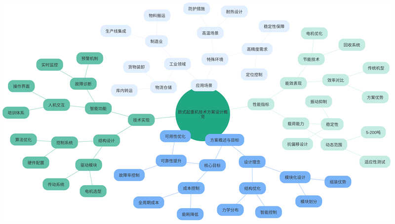
Modern industry places higher demands on material handling equipment. European cranes, with their compact structure, precise control, and high energy efficiency, have become core equipment in factories, workshops, logistics warehouses, and other locations. This technical solution combines advanced European design concepts with localized engineering experience to provide customized solutions for diverse working conditions. This solution encompasses comprehensive system innovations from structural design to intelligent control, strictly adhering to international safety and energy efficiency standards to ensure superior performance throughout the equipment’s lifecycle. Through modular design and digital management, it improves crane operational efficiency and ease of maintenance, creating greater value for modern manufacturing enterprises.
The European crane technology solution is an innovative design concept designed to improve industrial material handling efficiency, reduce costs, and enhance equipment reliability. Core to this solution is modular design, optimizing structural mechanical distribution and intelligent control algorithms to achieve high adaptability and efficient operation.
In industrial scenarios, cranes are indispensable material handling equipment. However, traditional crane designs often suffer from limitations such as poor adaptability, low efficiency, and high energy consumption. To address these issues, the European crane technology solution adopts a modular design concept. By dividing the crane into different modules, such as the drive module, control system module, and structural module, the equipment can be quickly assembled and repaired, while also facilitating upgrades and customization.
In terms of load capacity, the European crane technology solution is optimized for the load requirements of different industrial scenarios. By optimizing the structural mechanical distribution and intelligent control algorithms, the crane ensures stable operation within the 5-200 ton load range and guarantees efficient and reliable material handling.
In terms of design objectives, the European crane technology solution focuses on reducing equipment lifecycle costs. By optimizing the design and control algorithms, the solution achieves a balance between cost, reliability, and efficiency. Furthermore, the solution keeps the failure rate below 0.5%, improving equipment reliability and availability. Furthermore, by optimizing components such as the control system and motor drive, energy consumption is reduced by 20% compared to traditional models, reducing equipment energy costs.
In addition to its technical advantages, the European crane technology solution also places particular emphasis on a user-friendly human-machine interface. The simple and intuitive user interface enables operators to quickly master equipment operation after standard training. Furthermore, the solution provides a wealth of fault diagnosis and monitoring features, enabling operators to promptly understand equipment status and address issues.
The design strictly adheres to the FEM 1.001 standard to ensure that the structural safety factor meets requirements. The main beam is constructed of Q690D high-strength steel plate, which offers excellent mechanical properties and weldability, capable of withstanding various complex operating conditions and loads. Advanced welding techniques are employed to ensure reliable weld quality, and critical welds undergo 100% ultrasonic testing to ensure that weld quality meets requirements. The hoisting mechanism is equipped with a dual braking system consisting of a service brake and a safety brake. These two independently operated systems ensure rapid stopping of the equipment in an emergency. This design complies with the EN 13001-3-1 load spectrum requirements, ensuring equipment stability and safety. The electrical system achieves IP54 protection, protecting it from water and dust intrusion. All exposed moving parts are shielded to prevent contact, further enhancing equipment safety. These measures ensure stable operation in ambient temperatures ranging from -20°C to +50°C, providing reliable support for production.
The power system utilizes an IE4 energy efficiency-rated variable-frequency motor, characterized by high efficiency and low energy consumption, providing stable and efficient power to the equipment. To further improve energy utilization, a regenerative braking energy recovery device is also installed. This device converts energy generated during braking into usable electricity, increasing the energy utilization rate to 92%, thereby achieving the goal of energy conservation and emission reduction. The hoisting mechanism utilizes a four-drum differential arrangement, which controls the wire rope deflection angle within 0.5°, effectively reducing friction loss between the wire rope and the drum, and improving the equipment’s operating efficiency and service life. The operating mechanism is equipped with an automatic lubrication system that intelligently adjusts the lubrication cycle based on operating time to ensure sufficient lubrication during operation, reducing friction loss in the mechanical transmission and maintaining a mechanical transmission efficiency of over 98%. These measures, together, constitute the high efficiency and energy-saving design principle, not only improving the equipment’s operating efficiency and service life, but also providing reliable production support.
The control system integrates a PLC and IoT module, collecting real-time equipment operating data and processing and analyzing the data through a cloud-based management platform. A machine learning-based condition prediction algorithm has been developed, capable of providing 200 hours of advance warning of potential failures, enabling preventive maintenance and management of equipment. The remote diagnostic system supports 5G network connectivity, allowing technical experts to remotely guide on-site repairs using AR glasses, improving maintenance efficiency and equipment availability. The operator interface features a 10-inch touchscreen display that displays equipment operating parameters and maintenance reminders, allowing operators to monitor equipment status and take appropriate actions at any time. These measures, collectively forming the design principles of intelligent management, not only improve equipment management and maintenance efficiency, but also provide reliable support for production.
The main beam structure is a key component of the entire crane design. We chose an off-track box beam. This structure offers excellent load-bearing performance and stability, capable of withstanding large bending moments and shear forces. The mid-span camber is preset to L/1000, ensuring that the main beam will not permanently deflect due to loads over long-term operation. The web thickness is determined based on the gradient of the bending moment diagram, ensuring the strength and stability of the entire structure.
The end beam is another critical component of the crane, supporting the crane’s operating mechanism and loads. We use a three-in-one drive unit, which offers high torsional rigidity and ensures the stability and reliability of the end beam during operation. The GN·m²-level torsional rigidity ensures that the end beam will not deform or damage even when subjected to heavy loads.
The trolley operating mechanism is a crucial component of the crane, responsible for its lateral movement. We use forged 45# steel wheels, which are highly hard and wear-resistant, ensuring the stability and reliability of the crane during operation. The tread hardness requirement of HB300-350 ensures that the wheels will not deform or damage under high pressure. The wheel flange height is 1.2 times the tread width, ensuring the crane’s stability during operation.
All steel components undergo sandblasting during production to remove surface impurities and oxides, increase surface roughness, and enhance coating adhesion. The epoxy zinc-rich primer, with a thickness of at least 80μm, offers excellent corrosion and wear resistance, ensuring the steel components maintain their performance in humid and corrosive environments.
The hoisting motor utilizes a YZP series variable-frequency speed-regulating motor, which offers high efficiency and excellent speed regulation, meeting various operating requirements. A standard duty cycle requirement of 40% ensures the motor’s stability and reliability during long-term operation. Insulation Class F ensures excellent insulation performance even in high-temperature environments. The reducer utilizes hardened gears with a transmission ratio of 1:31.5, ensuring stability and reliability during crane operation. Gear precision meets ISO Class 6 requirements, ensuring accurate and stable transmission.
The wire rope utilizes a 35W×7 construction, which offers high strength and wear resistance, ensuring safety and reliability during lifting. A nominal tensile strength of 1960 MPa ensures the rope will not break or damage even under high tension. A rotating anti-twist device prevents kinking during use, ensuring smooth operation.
The power supply system utilizes an enclosed busbar design, ensuring stability and reliability. The inter-pole insulation resistance requirement of at least 10 MΩ ensures insulation performance and safety.
The control core utilizes a Siemens S7-1500 PLC, featuring high processing speed and stable performance, ensuring the reliability and stability of the control system. A scan cycle of ≤1 ms ensures rapid and accurate signal processing. The PROFINET communication module enables centralized control and management of multiple devices, improving production efficiency.
The inverter’s output frequency resolution of 0.01Hz ensures stability and accuracy during operation. The torque control accuracy of ±2% ensures smooth and safe operation during crane starting and braking.
We have also developed a dedicated HMI interface with 12 functional modules, including load display, fault logging, and maintenance reminders, allowing operators to more easily understand the crane’s operating status and production progress. The wireless remote control system operates at a 2.4GHz frequency, increasing its range and anti-interference capabilities, making operation more flexible and convenient. 128-bit AES encryption ensures data security and privacy during wireless communication.
The lifting height limiter uses an absolute encoder for precise height control, achieving a repeatable positioning accuracy of ±1mm, ensuring accurate and stable height control. An overload protection device effectively prevents accidents caused by overloading. The 110% rated load alarm and 125% automatic shutoff functions ensure safety and reliability during production. Hydraulic buffers installed at both ends of the trolley’s travel absorb ≥5000J of energy, acting as a buffer in the event of a collision and reducing damage to the equipment. Emergency stop buttons are arranged every 20 meters along the track, with a response time requirement of ≤50ms, ensuring operators can quickly stop the equipment and avoid accidents. The anti-collision system uses laser ranging technology with a detection range of 30 meters and an angle coverage of ±45°, effectively preventing collisions during crane operation and improving production safety and efficiency.
During installation, the rail straightness deviation must be less than or equal to 1/1000, and the joint clearance should be controlled within a range of 4-6mm. To ensure the stability and safety of the crane, a 200-ton truck crane was used for assembly, and the misalignment of the main beam joints was maintained within 2mm. For high-strength bolt connections, the torque deviation should be controlled within ±5%, and inspection should be completed within 48 hours of final tightening.
Electrical wiring should be laid 300mm away from power lines, and the shielding layer should be single-point grounded. These measures are designed to prevent electrical interference and ensure proper operation of the equipment.
A no-load test run is a key step in verifying equipment performance. It involves raising and lowering the hoisting mechanism three times throughout its full stroke and performing five reciprocating strokes of the operating mechanism. These tests verify smooth and accurate operation. Load testing is conducted at 25%, 50%, 75%, 100%, and 110% of the rated load to verify equipment performance under varying loads. Dynamic testing examines the equipment’s dynamic performance during operation, including: static deflection of the main beam ≤ L/800 and dynamic deflection ≤ L/1000. These tests check the equipment’s stability and vibration. Noise testing is conducted at a distance of 1 meter from the sound source, with a requirement of ≤ 75dB(A). These measures ensure that the equipment’s operation does not significantly impact the surrounding environment.
To ensure the quality and safety of installation and commissioning work, a three-level inspection system is necessary. Construction teams should be responsible for self-inspection to ensure that each step meets requirements. The project department should assign dedicated inspection personnel to conduct re-inspections of the work. The supervision unit is responsible for the final re-inspection. These measures can help identify and correct problems promptly, preventing potential safety hazards and quality issues.
It is also crucial to establish WHS control points at key processes. These control points include 12 nodes, such as rail pressure plate welding and main beam docking. These nodes are critical to equipment installation and commissioning and must be strictly controlled to ensure smooth progress. Testing instruments must undergo metrological verification before use to ensure their accuracy and reliability. Original records of measurement data must be retained for traceability and review. Commissioning reports must include 32 performance parameters, and acceptance can only be conducted after all meet the standards. These measures ensure that the performance and quality of the equipment meet expected requirements.
Daily inspections include: brake pad wear (<30% of original thickness) and broken wire ropes (<10% of total wire count). Lubricate open gear pairs weekly with NLGI Grade 2 lithium grease. Test the emergency stop function monthly, and record the response time. Clean the electrical cabinet and tighten all terminals quarterly.
Regular Maintenance Requirements
Annual maintenance requires replacing the reducer lubricant (ISO VG 320) and testing the motor insulation resistance (≥1MΩ). Perform nondestructive testing of the main beam every two years, and inspect 20% of welds with magnetic particle inspection. Replace hydraulic system seals and test buffer performance every three years. Perform load testing every five years to review the stress distribution of the steel structure.
Fault Diagnosis and Troubleshooting
A code library has been established for common faults: E001 indicates overcurrent protection; check the inverter parameters; E205 indicates an encoder fault; clean the grating disk. For complex faults, use a vibration analyzer to collect bearing frequency spectra. For electrical faults, a thermal imager is used to locate hot spots. For mechanical faults, a laser alignment tool is used to check concentricity. Major repairs require a 75% load retest.
Contact our crane specialists
Send us a message and we will get back to you as soon as possible.