The technical requirements for large-scale lifting equipment in the heavy industrial equipment sector are becoming increasingly stringent. The 600-ton gantry crane, as a key piece of equipment in modern heavy manufacturing, shipbuilding, and energy engineering, has technical specifications that directly impact the implementation efficiency and safety of major engineering projects. This specification systematically standardizes the entire process of technical standards from structural design to acceptance testing, highlighting the special performance parameters and safety redundancy design of high-tonnage lifting equipment. Addressing the reliability of equipment under extreme working conditions, the technical document defines core indicators such as material selection, load distribution, and dynamic stability in detail, providing quantifiable technical basis for the entire lifecycle management of the equipment.
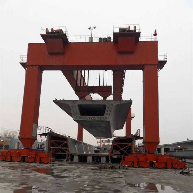
This project plans to purchase one double-girder gantry crane with a rated lifting capacity of 600 tons. The crane features a box-type main girder structural design to meet high-intensity operational demands and ensure long-term stable operation. The purchase quantity is determined scientifically and reasonably based on the actual needs of the port container terminal expansion project and anticipated load growth trends. It aims to ensure an annual throughput increase to 1.5 million TEUs upon project completion, thereby further enhancing logistics efficiency and reducing operational costs.
Table 1: Basic Equipment Information
| Equipment Name | Quantity | Delivery Date | Rated Lifting Capacity | Structural Type | Main Application | Working Range Dimensions | Applicable Standards |
|---|---|---|---|---|---|---|---|
| Double-Girder Gantry Crane | 1 Unit | _ | 600 Tons | Box-Type Main Girder | Heavy Equipment Lifting, Large Component Transport | 180m × 60m | GB/T 3811-2008, ISO 4306-1:2007 |
Table 2: Technical Documentation Requirements
| Document Type | Compilation Standard | Compilation Depth Requirement | Included Content | Purpose | Related Equipment |
|---|---|---|---|---|---|
| Technical Document | GB/T 3811-2008 | Detailed Design Stage | 3D Model Files | Equipment Manufacturing & Installation | Double-Girder Gantry Crane |
| Technical Document | ISO 4306-1:2007 | Detailed Design Stage | Finite Element Analysis Report | Structural Safety Verification | Double-Girder Gantry Crane |
| Process File | _ | _ | Full Set of Manufacturing Process Cards | Production Quality Control | Double-Girder Gantry Crane |
This crane is specifically designed for lifting heavy equipment and transporting large components. Its working range covers a rectangular area of 180 meters in length and 60 meters in width. The crane is capable of handling various special-shaped loads, such as containers, wind turbine blades, and pressure vessels. The effective lifting height within the span is 32 meters above the rail.
The compilation of technical documentation is a critical part of the entire project and must adhere to strict norms and standards. The technical documentation for this project must comply with the GB/T 3811-2008 “Crane Design Code” and the ISO 4306-1:2007 standard system. The depth of documentation shall meet the requirements of the detailed design stage, including 3D model files, finite element analysis reports, and a complete set of manufacturing process cards.
The equipment structure is designed as a double rigid leg box-girder type, which offers high strength and stability, ensuring safe operation under various working conditions. The main girder cross-section height reaches 3.2 meters, providing sufficient load-bearing capacity and stability. For ease of maintenance and inspection, the equipment is equipped with two levels of maintenance platforms, allowing easy access to all components. Functional modules integrate a spreader automatic rotation system, load dynamic monitoring unit, and anti-sway control system, ensuring a high degree of automation and safety. The main hoisting mechanism is configured with 4 independent winch units, providing greater lifting capacity and stability.
The design life and maintenance cycle of the equipment are carefully designed and tested to ensure long-term stable operation. The design life of structural components is not less than 30 years, and the design life of mechanism components reaches 100,000 working cycles. These design parameters guarantee the durability and reliability of the equipment. The maintenance cycle for key moving parts is set at 500 working hours, meaning necessary maintenance and inspection are required after these hours of operation. The interval for major overhauls of the entire machine is no less than 5 years, ensuring long-term stable operation.
In addition to the basic design codes, the equipment must meet numerous specific standards, including GB/T 5905-2011 “Test Code and Procedures for Cranes”, JB/T 1306-2008 “Electric Single Girder Cranes”, and 21 other specific standards. These are nationally and internationally recognized standards ensuring equipment performance and quality. Welding procedure qualification follows the AWS D1.1/D1.1M:2020 standard, guaranteeing professional and reliable welding quality.
Table: Comparison of International/Domestic Standards (ISO/GB/IEC, etc.)
| Standard Type | Standard Number | Standard Name | Scope of Application | Equivalent International Standard | Maintenance Cycle | Design Life Requirement |
|---|---|---|---|---|---|---|
| National Standard | GB/T 5905-2011 | Test Code and Procedures for Cranes | Crane Performance Testing | ISO 4309:2017 | Major Overhaul 5 Years | Structural Components ≥30 Years |
| Industry Standard | JB/T 1306-2008 | Electric Single Girder Cranes | Single Girder Crane Design | _ | 500 Working Hours | Mechanism Components 100k Cycles |
| International Standard | AWS D1.1/D1.1M:2020 | Structural Welding Code | Welding Procedure Qualification | ISO 3834-2:2005 | _ | _ |
| National Standard | GB/T 3811-2008 | Crane Design Code | General Design Principles | ISO 8686-1:2012 | _ | Whole Machine ≥20 Years |
| International Standard | ISO 12488-1:2012 | Crane Wheels and Tracks | Travel Mechanism Design | _ | 1000 Working Hours | Wheel Assembly ≥50k Hours |
Table: Equipment Key Parameters vs. Design Specifications
| Design Element | Technical Parameter | Implementation Standard | Test Method | Safety Factor | Monitoring Requirement | Maintenance Requirement |
|---|---|---|---|---|---|---|
| Main Girder Structure | Box Girder 3.2m High | GB/T 3811-2008 | Static Load Test ≥1.25x | 1.45 | Dynamic Stress Monitoring | Annual NDT |
| Hoisting Mechanism | 4 Sets Winch Units | ISO 4306-1:2007 | Dynamic Load Test ≥1.1x | 1.33 | Load Limiter | Lubrication every 500h |
| Welding Process | Full Penetration Weld | AWS D1.1/D1.1M | Ultrasonic Testing | _ | Heat Affected Zone Monitoring | Periodic Crack Inspection |
| Electrical System | IP54 Protection Level | IEC 60204-32:2008 | Insulation Resistance Test | _ | Temperature Monitoring | Quarterly Inspection |
| Anti-Sway System | ±50mm Accuracy | GB/T 31052.1-2014 | No-load Swing Test | _ | Real-time Position Feedback | Monthly Calibration |
The total span of the crane is 58 meters, with cantilever lengths of 12 meters each, resulting in a total coverage range of 82 meters. These dimensions ensure operational requirements under various complex conditions. The crane height above the rail is 42 meters, and the clearance from the bottom of the main girder to the rail is 9.5 meters. This data not only meets the requirements for the passage of oversized equipment but also ensures stability and safety during operation.
The main hook has a rated lifting capacity of 600 tons (four lifting points), while the auxiliary hook has a capacity of 100 tons. This configuration meets the lifting needs for loads of various weight classes. Regarding hoisting speed, the main hook speed is adjustable from 0.5-5 m/min, and the auxiliary hook speed is adjustable from 1-10 m/min. This design allows for precise speed control during operations. For full-load lowering, an energy consumption braking method is used, ensuring stability and safety.
The gantry travel speed is 20 m/min, equipped with 16 sets of motorized wheel assemblies, ensuring stable and smooth travel. The trolley travel speed is 30 m/min, adopting an integrated three-in-one drive form, which offers simple structure and reliable operation. The rail profile is QU120, with a foundation bearing capacity requirement of ≥25 t/m². This design ensures the crane does not experience shaking or tilting during operation, further enhancing operational safety and efficiency.
The structural design fully considers a 50-year return period wind pressure value of 1.2 kN/m² to ensure stability and safety under extreme weather conditions. The operational wind resistance capability reaches 20 m/s, effectively resisting strong wind impacts. For electrical components, products with IP54 protection level are selected, ensuring good performance even in dusty or humid environments. To adapt to low-temperature environments, low-temperature hydraulic oil capable of normal operation at -30°C is specifically selected, ensuring smooth operation in cold regions. For high-temperature conditions, an efficient forced cooling system is configured to maintain stable internal temperatures and prevent performance degradation or failure due to overheating.
For seismic design, the equipment strictly adheres to the requirements for a seismic fortification intensity of 8 degrees, ensuring it maintains a secondary structural seismic grade under external vibrations such as earthquakes. Major steel structural components undergo Sa2.5 grade shot blasting during production to improve surface roughness and adhesion, facilitating coating application and corrosion resistance. A three-layer heavy-duty anti-corrosion coating system is applied, providing strong protection against various corrosive media and extending the equipment’s service life. Cathodic protection measures are also implemented at key connection points, further reducing metal corrosion rates through electrochemical principles, ensuring the equipment remains in good condition throughout its long-term use.
The power supply scheme introduces a 10kV high-voltage incoming line, which is stepped down by a transformer to provide a stable power supply capacity of 2500 kVA. To ensure reliability and stability, the distribution system is specially configured with 4 independent circuits, allowing rapid switching to other circuits in case of a fault in one, ensuring uninterrupted power supply. Additionally, an emergency power system is equipped to maintain the operation of critical mechanisms for at least 30 minutes in case of mains power failure, ensuring the normal operation of important equipment and data security. In the variable frequency drive system, advanced common DC bus technology is adopted, improving energy utilization efficiency, reducing energy consumption, while also reducing equipment volume and weight, and simplifying the system structure, making the entire drive system more efficient, reliable, and compact.
A fully digital control system is adopted, integrating PLC (Programmable Logic Controller) and touch screen interface, offering not only simple and intuitive operation but also powerful functional integration and computational capabilities. The system supports remote monitoring, allowing management personnel to grasp equipment status and production data in real-time; the built-in fault diagnosis function can detect and warn of potential issues promptly, greatly improving operational efficiency and reducing fault resolution time. The master controller uses advanced CAN bus communication technology, featuring high speed, high reliability, and powerful network node connection capability, conducive to improving overall equipment control performance. For position detection, absolute encoders are used with an accuracy of ±10mm, ensuring precise equipment positioning and effectively preventing positioning deviations due to accumulated errors.
To ensure safe equipment operation and prevent accidents, the system is configured with triple load protection measures. Firstly, the electronic weighing system monitors the equipment load in real-time; if the set threshold is exceeded, an alarm is triggered immediately, and corresponding measures are taken to prevent damage from overloading. Secondly, the mechanical overload limiter restricts the maximum load through precise mechanical structure, ensuring operation within safe limits. Finally, the hydraulic safety valve regulates the hydraulic system pressure, preventing equipment failure or safety incidents due to excessive pressure.
In addition to overload protection, the system also uses redundantly designed travel limit devices to ensure the equipment does not exceed the set travel range. Contact-type limit switches detect the equipment’s position via mechanical contacts, while non-contact photoelectric detection uses sensors. The two limit methods are independent of each other, enhancing system reliability and safety.
To ensure the equipment does not move unexpectedly or overturn under wind force, the system is equipped with two sets of windproof devices: automatic rail clamps and hydraulic rail jacks. The automatic rail clamps secure the equipment by gripping the rails, while the hydraulic rail jacks secure it via hydraulic cylinders pressing against the rails; the two devices serve as backups for each other, ensuring equipment stability. Furthermore, anchor pits are set up, fixing the equipment to the foundation through anchoring devices, further enhancing wind resistance.
The wind speed monitoring system monitors the ambient wind speed in real-time. When the wind speed exceeds 17 m/s, the system issues a warning prompt. When the wind speed reaches 20 m/s, an automatic shutdown procedure is triggered, ensuring operational safety.
The manufacturing process of the steel structure is a key link in ensuring structural quality and performance. For key components like the main girder, a segmented manufacturing approach is adopted, with each segment length strictly controlled within 18 meters to ensure the quality and safety of welded joints. Simultaneously, all butt welds undergo 100% ultrasonic testing to ensure the welds are free from cracks, lack of fusion, incomplete penetration, and other defects, guaranteeing weld quality and strength. During material cutting, advanced CNC plasma cutting technology is used to ensure precision and efficiency. For important load-bearing nodes, such as welded joints and connection plates, phased array testing is implemented to more accurately assess the mechanical properties and safety of the nodes.
During the on-site installation phase, a detailed installation plan is formulated. Firstly, a 1600-ton crawler crane is used for the main girder lifting. The crawler crane has a large lifting capacity and flexible mobility, ensuring stability and safety during the lifting process. Meanwhile, to ensure the verticality and stability of the steel structure, the verticality of the legs is strictly controlled, with deviation not exceeding H/2000. The installation accuracy of the rails is also a crucial factor affecting the overall performance of the steel structure; the rail span deviation is ensured to be within ±10mm, and the rail level difference does not exceed 5mm/10m. The implementation of these measures will significantly improve the installation quality and safety of the steel structure.
The core auxiliary devices used in this equipment are from top-tier brands renowned in the industry. Firstly, the imported German wire rope offers extremely high strength and wear resistance, ensuring stable equipment operation; the Swedish SKF bearing sets guarantee smooth rotation with their exceptional precision and load capacity; the Siemens 7.5MW drive motor provides powerful and reliable motive power. For the hydraulic system, the Rexroth pump station and accumulator unit combination makes the system more stable and efficient. The double-acting pushrod electromagnetic-hydraulic type brakes provide reliable braking assurance with their sensitivity and durability.
To ensure long-term stable operation of the equipment, 36 categories of wear parts are provided, including wire rope, brake linings, and collector carbon brushes. The quantity of these wear parts is sufficient for 2 years of normal consumption. Additionally, 3 complete sets of pulley block assemblies are provided to ensure continuous and efficient equipment operation.
Table: Key Spare Parts List (Including Model, Quantity, Replacement Cycle)
| Spare Part Name | Model/Brand | Quantity | Replacement Cycle | Remarks |
|---|---|---|---|---|
| Wire Rope | Imported German High-Strength Type | 2 Coils | 18 Months | Excellent Wear Resistance |
| SKF Bearing Set | Swedish SKF Precision Bearing | 4 Sets | 24 Months | High Precision Load Capacity |
| Siemens Drive Motor | 7.5MW High-Efficiency Type | 1 Unit | 60 Months | Core Power Component |
| Rexroth Pump Station | Dedicated for Hydraulic System | 1 Set | 36 Months | Includes Accumulator Unit |
| Brake Lining | Double-acting Pushrod Electro-Hydraulic Type | 12 Pairs | 12 Months | High Sensitivity Braking |
| Collector Carbon Brush | Standard Conductive Graphite Type | 24 Units | 6 Months | Require Regular Inspection/Replacement |
| Pulley Block Assembly | Dedicated for Heavy Loads | 3 Sets | _ | Complete Standby Component |
Table: Core Auxiliary Device Technical Parameters
| Device Name | Brand/Model | Key Characteristics | Design Life | Maintenance Requirement | Application Scenario |
|---|---|---|---|---|---|
| Wire Rope | Imported German | High Strength, Wear Resistant | 10 Years | Regular Lubrication & Inspection | Heavy Lifting Equipment |
| SKF Bearing Set | Swedish SKF | High Precision, High Load Capacity | 8 Years | Quarterly Lubrication Maintenance | Core Component of Rotating Machinery |
| Siemens Drive Motor | 7.5MW High-Efficiency Type | Efficiency ≥95%, IP55 Protection | 15 Years | Annual Insulation Test | Main Drive System |
| Rexroth Hydraulic System | Pump Station + Accumulator | Stable Pressure 35MPa, Fast Response | 12 Years | Replace Hydraulic Oil Semi-annually | Precision Control Hydraulic Mechanism |
| Electro-Hydraulic Brake | Double-acting Pushrod Type | Braking Torque ≥5000Nm, 0.1s Response | 5 Years | Monthly Braking Performance Test | Safety Braking System |
During the manufacturing process, 100% re-inspection of incoming materials is conducted to ensure every material meets relevant standards and requirements. For welding test plates, one set of welds is performed every 50 linear meters to ensure welding quality. Simultaneously, dimensional tolerances for structural components adhere to the EN 1090-2 EXC3 grade, which is an industry standard and reflects our strict quality requirements. Furthermore, after mechanism assembly is completed, a 72-hour bench test is conducted to verify its performance and stability.
For on-site acceptance testing, comprehensive tests are carried out. These include a no-load test, which is a full-stroke operation test to check for smooth equipment operation. In the static load test, 1.25 times the rated load is applied to test the load-bearing capacity. In the dynamic load test, 1.1 times the load is applied to check the dynamic performance. Additionally, structural deformation is measured at no less than 32 monitoring points to ensure the deformation of structural members is within acceptable limits. Finally, mechanism temperature rise is monitored for a duration of 4 hours to ensure operational stability and safety.
The basic technical documents delivered for this project cover the core design content, including but not limited to 12 sets of paper blueprints for general assembly drawings and component drawings. These blueprints are drawn according to national standards and industry norms, each set including detailed design descriptions, drawings, calculation books, and related technical requirements. Additionally, one copy of the 3D model data package consistent with the paper blueprints is provided for subsequent design modifications, production processing, and installation commissioning. To ensure smooth project progression, 26 special analyses have been conducted on key performance aspects such as structural strength, stiffness, and stability, with detailed calculation books compiled as proof.
To provide comprehensive technical support, the delivery also includes 5 sets each of operation and maintenance manuals in both Chinese and English. The maintenance manuals detail equipment operation procedures, maintenance requirements, and common fault handling methods, aiming to help users better master equipment performance and usage skills. Simultaneously, a set of training video materials is provided to further enhance users’ operational skills and theoretical knowledge through intuitive and vivid video teaching. Furthermore, the developed intelligent management system includes equipment health assessment modules and remaining life prediction algorithms, enabling real-time monitoring of equipment status, accurate assessment of equipment health, and prediction of the remaining service life. This intelligent management system will significantly improve equipment operation and maintenance efficiency and reduce costs.
Contact our crane specialists
Send us a message and we will get back to you as soon as possible.