As an indispensable material handling equipment in modern industrial production, the design quality of the trolley running mechanism of a bridge crane is directly related to the performance, safety, and reliability of the entire machine. This article comprehensively explores the design process of a bridge crane’s trolley running mechanism, from structural composition to drive mode selection, from design calculations to component selection, systematically introducing each key aspect of trolley running mechanism design. By integrating theoretical calculations with engineering practice, this article provides crane designers with a comprehensive set of design ideas and methods. It also considers the latest technological trends and explores the future direction of trolley running mechanism design.
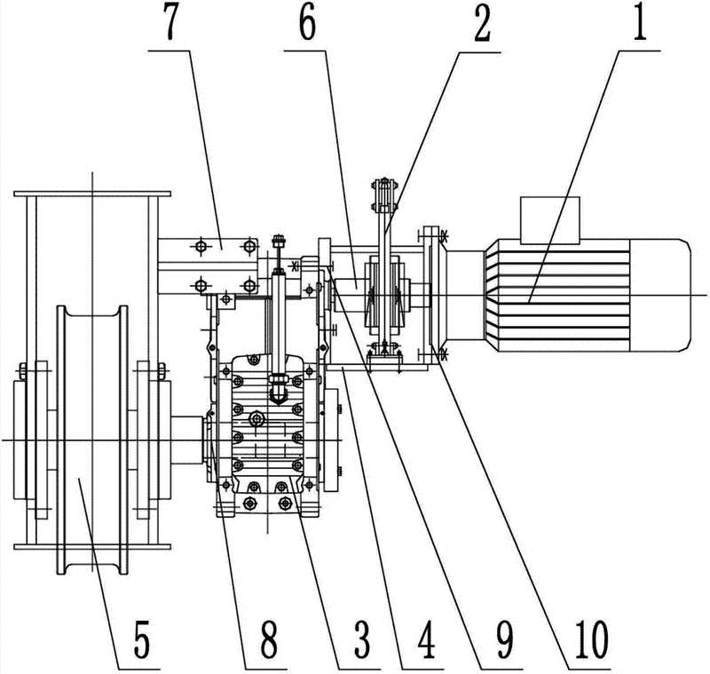
The trolley running mechanism of a bridge crane is the crane’s moving mechanism, responsible for longitudinal movement along the elevated tracks on both sides of the workshop to facilitate material transfer. As one of the core components of a bridge crane, the performance of the trolley running mechanism directly affects the crane’s operating efficiency, operational stability, and safety. A typical trolley running mechanism consists of several major components: the drive unit, transmission system, support structure, and safety devices. These components include the motor, controller, coupling, drive shaft, reducer, angular bearing housing, and trolley wheels.
The basic operating principle of the trolley mechanism is that power provided by the electric motor is decelerated and amplified by the transmission system, ultimately driving the wheels to roll on the rails, thereby achieving longitudinal movement of the entire bridge. The design parameters and configuration of the trolley mechanism vary significantly depending on the crane’s span, load capacity, and operating environment. For example, for a 10-ton, mid-range bridge crane with a span of 22.5 meters, the trolley operating speed is typically designed to be around 43.8 m/min, and the mechanism’s operating duration (JC%) is approximately 25%. In contrast, larger-tonnage cranes, such as 16-ton general-purpose bridge cranes, require a stronger driving capability and more rigorous strength verification for their operating mechanisms.
The design of a trolley running mechanism must meet a series of basic requirements: first, safety and reliability, ensuring stable operation under all operating conditions and preventing derailment, overturning, and other accidents; second, operational smoothness, minimizing shock and vibration during starting and braking to ensure the stability of the hoisted load; third, cost-effectiveness, optimizing the design while meeting performance requirements to reduce manufacturing costs and energy consumption; and finally, ease of maintenance, considering component accessibility and replaceability to facilitate routine maintenance and repair.
Depending on the drive method, trolley running mechanisms can be divided into two types: centralized drive and separate drive. Centralized drive is a traditional drive method in which a single motor drives both wheels synchronously via a drive shaft, while separate drive is a modern drive method in which each wheel set is driven by an independent motor, eliminating the need for long drive shafts. With the advancement of motor control technology, separate drive has become the mainstream design for trolley running mechanisms, owing to its significant advantages such as simple structure, flexible layout, and easy installation and maintenance.
The metal structure of a trolley running mechanism primarily includes components such as the main beam, end beams, platform, and guardrails. The main beam and end beams typically utilize a box-section structure welded from steel plates. This box-section structure boasts high rigidity, strength, and a mature manufacturing process, effectively bearing various loads and ensuring the overall stability of the bridge. The main beam’s upper, web, and lower covers are welded together to form a closed box, with stiffening ribs installed internally as needed to enhance local stability.
The trolley travel mechanism’s drive method is a key decision in the overall system design, directly impacting crane performance, energy consumption, and maintenance costs. As mentioned earlier, bridge crane trolley travel mechanisms are primarily categorized into two basic drive methods: centralized drive and separate drive. Each method has its own unique advantages and disadvantages and applicable scenarios.
A centralized drive system is a traditional drive system. Its typical configuration involves a single motor driving both wheel sets simultaneously via a coupling, a long drive shaft, and a speed reducer. In this arrangement, the motor is typically mounted in the center of the bridge. Power is transmitted to both wheels via a drive shaft, which is then reduced and amplified by the speed reducer before being transmitted to the wheels. The primary advantage of a centralized drive system is that it ensures synchronization of the wheels on both sides, as all wheels are driven by the same power source, theoretically eliminating speed differences. Furthermore, centralized drive requires only a single motor and control system, resulting in relatively low equipment costs, making it advantageous for small-span cranes.
However, centralized drive systems also have significant limitations. The long drive shaft requires a complex support structure, increasing the weight of the mechanism and making installation more difficult. The longer the drive shaft, the greater its torsional elastic deformation, which can easily lead to asynchronous operation of the wheels on both sides, negating the theoretical advantages of centralized drive. Furthermore, long drive shaft systems suffer from significant energy losses, lower operating efficiency, and are more difficult to maintain and repair. Due to these drawbacks, the use of centralized drive in modern bridge cranes has gradually declined, primarily confined to lightweight cranes with smaller spans (generally less than 16.5 meters).
The separate drive system is the mainstream choice for the trolley travel mechanism of modern bridge cranes. Its characteristic is that each driving wheel set on each side is driven by an independent electric motor, with no mechanical connection between the two sides. Typically, a separate motor is installed on each side, driving the wheel set on the same side through a coupling and a speed reducer. The separate drive system eliminates the various problems associated with long drive shafts, simplifies the mechanical layout, reduces deadweight, and improves transmission efficiency. Since each side is independently driven, installation and maintenance are much simpler, a particularly significant advantage for long-span cranes.
The key technology of the separate drive system lies in ensuring the synchronous operation of the motors on both sides. Traditional electrical control methods use a parallel circuit to maintain the same input for both motors. However, in actual operation, deviation can still occur due to differences in motor characteristics, wheel diameter deviation, or varying track conditions. Modern cranes commonly use variable frequency speed regulation technology, which achieves high-precision synchronization of the two drive systems through speed feedback and closed-loop control, effectively solving the deviation problem. Separate drive systems also offer the advantage of redundant safety. If one drive fails, the other can continue to operate temporarily, allowing the crane to be moved to a safe location for maintenance.
When selecting a trolley travel mechanism drive system, several factors should be considered:
In actual engineering designs, separate drive has become the preferred solution for most trolley travel mechanisms on bridge cranes. For example, in the design of a 10-ton crane with a 22.5-meter span, although the span is not too large, separate drive may be more suitable given the working environment and ease of use and maintenance. For larger general-purpose bridge cranes, such as those with a tonnage of 16 tons, separate drives are almost the only option.
Notably, with the development of permanent magnet synchronous motors and direct drive technology, new drive methods are emerging, such as in-wheel motor drives, which integrate the electric motor directly into the wheel, further simplifying the drive train and improving efficiency. These innovative drive methods are expected to become the new standard for bridge crane trolley mechanisms in the future.
The design calculation for a bridge crane’s trolley traveling mechanism is a systematic process. Based on given technical parameters and operating conditions, a series of calculations and verifications are performed to determine the specifications and parameters of each component. This process not only impacts the crane’s performance but also directly affects the equipment’s safety and reliability. A typical design calculation process includes key steps such as wheel and track selection, running resistance calculation, motor selection, reducer matching, and brake selection.
The first step in trolley traveling mechanism design is to determine basic design parameters. These typically include the crane’s lifting capacity, span, operating range, operating speed, and estimated deadweight. For a typical 10-ton bridge crane, its basic parameters are: lifting capacity Q = 10 tons, bridge span L = 22.5 meters, trolley operating speed Vdc = 43.8 meters/minute, intermediate operating range, mechanism operating duration JC% = 25, estimated crane weight G = 168 kN, and trolley weight Gxc = 40 kN. These initial parameters provide the foundation for all subsequent calculations.
The selection of wheels and rails is a crucial aspect of crane running mechanism design. Wheel diameter directly affects running resistance and mechanism dimensions, while wheel material and rail type influence load capacity and service life. Typical box-type bridge crane designs typically utilize double-flange wheels to enhance derailment resistance, with wheel diameters typically ranging from 400-700mm. Wheel pressure calculation is crucial for selection, taking into account the crane’s deadweight, rated load, and load distribution. The maximum allowable wheel pressure should meet the following criteria:
Pmax ≤ [P]
Where [P] is the allowable wheel pressure, which depends on the wheel material and rail type. The calculation must consider the most unfavorable load combination, typically the crane’s deadweight plus the rated load, and factor in the impact factor φ (generally set at φ = 1.1-1.3).
The total running resistance W of a trolley is the basis for selecting motor power. It primarily consists of friction resistance Wm, slope resistance Wp, and wind resistance Ww. For indoor bridge cranes, wind resistance is generally negligible; when operating on flat tracks, slope resistance can also be ignored, making friction resistance the primary consideration. Friction resistance can be calculated using the following formula:
Wm = (Q+G)(μd+2f)/D
Where Q is the load capacity, G is the crane’s deadweight, μ is the bearing friction coefficient, d is the wheel axle diameter, f is the rolling friction coefficient, and D is the wheel diameter. Total running resistance W = Wm + Wp + Ww.
The motor’s static power Pj can be calculated as follows:
Pj = WVdc/(60η)
Where Vdc is the operating speed (m/min), and η is the transmission efficiency of the mechanism (usually 0.85-0.9). Taking into account the inertia force during crane startup, the motor’s rated power, Pn, should satisfy the following:
Pn ≥ Pj * k
k is the safety factor, generally set at 1.1-1.3. For a 10-ton crane, the calculated motor power is typically in the 3-5 kW range, while for a 16-ton crane, the motor power can reach 7.5-11 kW.
Gearbox selection should be determined based on the motor speed, transmission ratio, and output torque. First, calculate the transmission ratio i:
i = nmotor/nwheel = πDnmotor/Vdc
Where nmotor is the motor’s rated speed (rpm), and nwheel is the wheel speed (rpm). Based on the calculated transmission ratio and output torque, refer to the gearbox product catalog to select an appropriate model.
After selecting a gearbox, verify the deviation between the actual operating speed and the designed speed:
Vactual = πDnmotor/(iactual)
Speed deviation should be controlled within ±15%, otherwise it may affect crane performance. Additionally, verify that the actual required power is less than or equal to the selected motor’s rated power.
Starting time verification is a critical step in trolley travel mechanism design. Excessively long starting times can affect operating efficiency, while too short a time can result in excessive starting shock. Starting time tq can be calculated as follows:
tq = (Mq – Mj) ≤ [t]
Where J is the total moment of inertia of the mechanism, ω is the angular velocity, Mq is the average starting torque of the motor, and Mj is the static drag torque. [t] is the allowable starting time, typically set between 4 and 8 seconds.
Slip verification during starting is also essential to ensure sufficient adhesion to prevent wheel slip:
φPmin ≥ (Q+G)a/g + W
Where φ is the adhesion coefficient (typically 0.12), Pmin is the minimum drive wheel pressure, a is the starting acceleration, and g is the acceleration due to gravity. If these conditions are not met, increase the number of drive wheels or adjust the deadweight distribution.
Brake selection is based on braking torque calculation and must ensure reliable stopping within the specified braking distance:
Mz ≥ (Mj + J*ω/tz)
Where tz is the braking time, which is usually slightly less than the starting time tq. After selecting a brake, its compatibility with the motor must be confirmed, including installation dimensions and torque capacity.
Couplings include high-speed and low-speed couplings. High-speed couplings typically use flexible couplings with brake wheels to both transmit torque and provide a braking surface. Low-speed couplings are often rigid or gear couplings to withstand larger radial loads. The coupling’s rated torque should be greater than the calculated maximum operating torque, with a safety margin.
Table: Examples of main parameters for design and calculation of trolley travel mechanisms (taking a 10-ton bridge crane as an example)
| Parameter name | Calculation formula | Example Value | Remark |
| Wheel diameter | Select according to wheel pressure | 500mm | Double rims |
| Running resistance | W=(Q+G)(μd+2f)/D | 2.1kN | Ignore slope and wind resistance |
| Motor power | Pj=WVdc/(60η) | 4.2kW | Select 5.5kW motor |
| Gear ratio | i=πDn motor/Vdc | 23.4 | Use standard reducer |
| Start time | 5.2s | Meet the ≤8s requirement | |
| Braking torque | Mz≥(Mj+J*ω/tz) | 65Nm | Selection YWZ5-200/23 |
Through the above systematic design calculation and verification process, the key parameters and component specifications of the trolley running mechanism can be determined, providing a reliable basis for subsequent detailed design and technical drawings. These calculations require not only theoretical knowledge but also practical engineering experience and component supplier specifications to ultimately produce an economically sound, safe, and reliable design.
The performance and reliability of a bridge crane trolley running mechanism depend largely on the design and selection of its key components. A complete trolley running mechanism comprises multiple subsystems, including the drive unit, transmission system, wheel assembly, metal structure, and safety devices. Each subsystem has its own unique design points and technical requirements. A thorough understanding of the design principles and structural characteristics of these key components is crucial for designing an efficient and reliable trolley running mechanism.
The wheel assembly is the component of the trolley running mechanism that directly bears the load and rolls on the track. Its design quality directly affects the crane’s operating stability and lifespan. A typical trolley wheel assembly consists of a wheel, axle, bearing housing, bearings, and seals. Wheels are typically cast or forged from materials such as ZG340-640 or 42CrMo, and heat-treated to increase tread hardness (typically to 300-350 HB). Wheel diameter selection takes into account wheel load, operating speed, and life requirements, generally ranging from 400-700 mm.
The wheel tread is typically cylindrical, with flanges on both sides to prevent derailment. The flange height is generally 20-25 mm, and the thickness is 30-40 mm. To increase wheel life, modern cranes are increasingly using heat-treated or alloy steel wheels, especially for heavy-duty cranes. Wheel bearings are often spherical roller bearings, which can withstand radial loads while accommodating certain installation tolerances. Bearing housings typically utilize an angular design for ease of installation, adjustment, and maintenance.
Track design is also crucial. Common track types include P-type railway rails, QU-type crane rails, and square steel rails. The track model should be matched to the wheel diameter and wheel load. QU series crane rails are preferred due to their excellent fatigue resistance and low contact stress. Track gauge deviation, levelness, and straightness must be strictly controlled during installation. Generally, the gauge deviation should not exceed ±5mm, and the longitudinal track slope should not exceed 0.5%.
The transmission system of the trolley mechanism primarily consists of key components such as the motor, coupling, brake, and reducer. In a separate drive system, each side has an independent transmission system, typically employing a “motor-brake-reducer-wheel” layout.
The reducer is a core component of the transmission system, and its selection must consider factors such as the transmission ratio, input speed, output torque, and operating level. Common reducer types include the ZQ series cylindrical gear reducer, the QJ series medium-hardened gear reducer, and the three-ring reducer. In modern designs, hardened gear reducers are widely used due to their small size, light weight, and high load capacity. Reducers are typically mounted on a base, secured to the bridge frame with anchor bolts. The output shaft is connected to the wheel axle via a coupling.
The coupling provides both connection and buffering in the transmission system. High-speed shafts typically use elastic pin couplings with brake wheels to transmit torque and provide a braking surface. Low-speed shafts often use gear couplings or rigid couplings to withstand larger radial loads. When selecting a coupling, calculate its calculated torque:
Tc = K*T ≤ [T]
Where K is the operating factor, T is the operating torque, and [T] is the allowable torque of the coupling. For trolley travel mechanisms, a K value of 1.5-2.0 is generally used.
The metal structure of the trolley travel mechanism serves as the foundation for supporting and connecting various components, primarily consisting of end beams, connecting beams, and platforms. The end beams directly support the wheel assembly and are typically welded from a box section or composite steel. The box end beams are welded from upper and lower cover plates and a web, with internal stiffening ribs for improved local stability. The end beam height is generally 350-600mm and the width 250-400mm, depending on the span and wheel load.
The connecting beam connects the two end beams and, together with the main beam, forms the bridge structure. For large-span cranes, the connecting beams are typically designed in sections for ease of transportation and installation. A walkway is a platform installed on one or both sides of the bridge, used to install the trolley running mechanism and provide maintenance access. It is generally at least 600mm wide and equipped with guardrails.
Metal structure designs require strength and stiffness verification. Strength verification includes static and fatigue strength, taking into account the combined effects of deadweight, lifting load, inertia, and impact loads. Stiffness verification primarily controls deflection, typically requiring the vertical static deflection of the main beam at midspan to not exceed 1/800-1/1000 of the span. Furthermore, for higher-performance cranes, dynamic stiffness and vibration must also be considered. Generally, the bridge’s natural frequency is required to be no less than 2Hz.
The safety devices of the trolley operating mechanism are crucial for ensuring safe crane operation. They primarily include limit switches, buffers, anti-collision devices, and windbreaks.
Limit switches are used to limit the trolley’s operating range and prevent it from exceeding the effective track length. Typically, a first-level limit switch is installed at each end of the trolley’s travel range: the first is a deceleration limit, and the second is a stop limit. When the trolley reaches a preset position, the deceleration limit switch triggers, warning the operator to slow down to prevent excessive impact that could damage equipment or cause accidents. The buffer activates when the trolley approaches the end of the track. By absorbing the kinetic energy of the operating mechanism, it effectively mitigates the impact of the trolley striking the limit device, thereby protecting the trolley operating mechanism, track, and related structures.
Anti-collision devices are a key component of the trolley operating mechanism’s safety system, primarily used to prevent collisions when multiple trolleys are operating in conjunction. These devices typically use sensors to monitor the positions of surrounding trolleys in real time. If a collision risk is detected, they immediately activate a warning system or even automatically apply emergency braking, effectively preventing accidents caused by operator error or equipment failure. To address the potential impact of wind on trolley operations, windbreaks are designed to mitigate these effects. They utilize anchoring systems, wind deflectors, or other mechanical structures to disperse or offset the force of strong winds on the trolley, ensuring stable operation in strong winds. Windbreaks may also include an anemometer and wind vane for monitoring wind speed and direction, as well as a control system that automatically adjusts the trolley’s operating status based on this data.
Contact our crane specialists
Send us a message and we will get back to you as soon as possible.