As an indispensable piece of equipment in modern industrial production, the design of the trolley running mechanism and trolley frame of a bridge crane is directly related to the performance and reliability of the entire machine. This paper systematically analyzes the trolley running mechanism and trolley frame of a 10t bridge crane, detailing various aspects, including structural composition, design key points, calculation verification, and manufacturing processes. By integrating existing technical information and design specifications, this paper discusses the selection and calculation of closed gear transmission systems, optimization methods for wheel load uniformity, the mechanical properties of box-type welded structures, and the application of modular design concepts in crane trolleys. This provides a comprehensive and practical technical reference for the design and optimization of 10t bridge cranes.
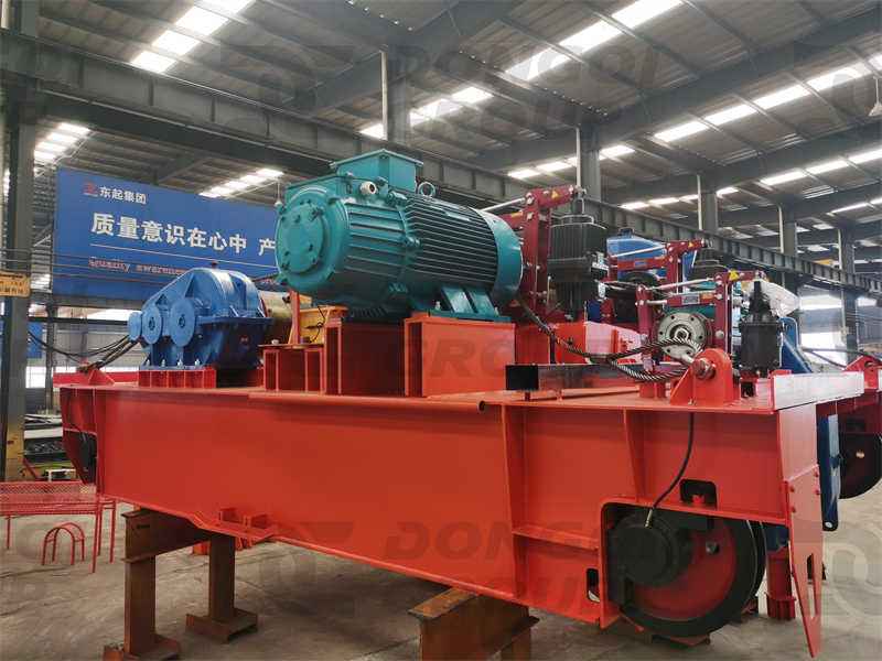
The trolley running mechanism of a bridge crane is the core component that enables horizontal movement of the load. Its design directly impacts the crane’s operating efficiency and reliability. The trolley running mechanism of a 10t bridge crane primarily consists of a drive motor, transmission system, running wheels, and a brake system. These components are integrated into the trolley frame to form a compact mobile unit. Depending on the crane’s operating class and conditions, the trolley mechanism must meet certain speed range requirements, ensure smooth starting and braking, and maintain long-term durability.
The selection of a transmission scheme is the primary step in trolley mechanism design. For 10t bridge cranes, the most common transmission schemes are closed gear and open gear. Closed gear transmission has become the mainstream choice for modern bridge crane trolley mechanisms due to its high transmission efficiency, low maintenance requirements, and long life. As described in the literature, this design employs a closed transmission scheme in which the motor is directly connected to the reducer, and the reducer output shaft is connected to the wheel axle via a coupling. This compact structure and short transmission chain not only improve transmission efficiency (reaching over 85%) but also reduce the mechanism size, contributing to the overall lightweighting of the trolley structure.
The basic operating parameters of the trolley mechanism must be determined based on the crane’s operating class and operating conditions. For a 10t bridge crane, the typical trolley operating speed ranges from 20 to 40 m/min. Excessively high speeds increase inertia during starting and braking, affecting operating smoothness; excessively low speeds reduce operating efficiency. The trolley mechanism of a 10t bridge crane mentioned in the literature utilizes a YZR180L-6 asynchronous motor with a power of 15kW, coupled with a QJ-L280 reducer with a transmission ratio of 20-40 and a wheel diameter of 400-500mm, meeting the requirements of most industrial applications.
The mechanism layout significantly impacts the trolley’s operating performance. The design should adhere to the “center of gravity” principle. This means rationally arranging components so that the mechanism’s center of gravity is close to the longitudinal centerline of the trolley frame, thereby achieving uniform wheel pressure distribution. The literature specifically emphasizes: “To achieve uniform wheel pressure distribution, the trolley’s mechanism layout should be optimized. Taking a known trolley track and wheelbase as an example, with uniform wheel pressure distribution as the objective function, constraints are proposed based on the conditions of a single-hook lifting trolley.” This layout approach, based on optimization theory, effectively avoids localized track wear and motor load imbalance caused by uneven wheel pressure.
Motor selection should consider the crane’s operating characteristics. Because crane trolleys require frequent starting, braking, and reversing during operation, wound-rotor asynchronous motors (such as the YZR series) are generally selected over conventional squirrel-cage motors. By connecting a resistor in series with the rotor circuit, wound-rotor motors achieve a wide speed regulation range and smooth starting characteristics. The motor’s rated power must meet the requirements for overcoming the trolley’s operating resistance (including friction, slope resistance, wind resistance, and inertia resistance), while leaving a certain power margin. Literature states: “The motor driving the hoisting machinery should be selected based on parameters such as required power, maximum torque, and starting characteristics.”
The braking system ensures the safe operation of the trolley mechanism. 10t bridge crane trolley mechanisms are typically equipped with YWZ5 series hydraulic push-rod brakes with a braking torque range of 20-50 Nm. The brake should automatically engage in the event of a power outage to prevent accidental trolley movement. For applications with higher requirements, a dual braking system or variable frequency speed control technology can be used for more precise speed control and parking positioning. The literature mentions that modern bridge crane trolley operating mechanisms have begun to apply “variable frequency speed regulation technology” to achieve smoother operating characteristics and precise positioning control.
The design of key components in the trolley mechanism directly determines its reliability, durability, and ease of maintenance. A thorough understanding of the operating principles and design key points of each component is crucial for optimizing the overall performance of the trolley mechanism of a 10t bridge crane. This section will detail the selection and design methods for core components such as the reduction gear, wheel assembly, coupling, and brake.
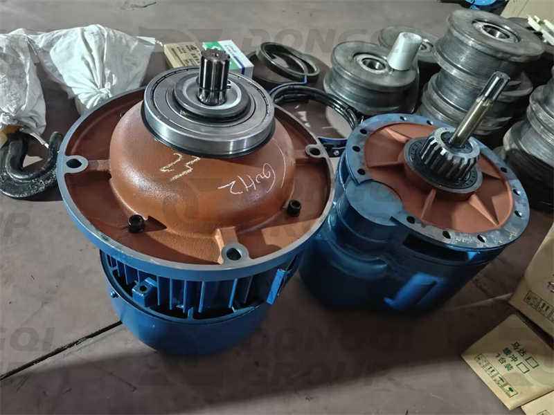
As the core transmission component connecting the motor and wheel assembly, the reducer’s selection requires comprehensive consideration of factors such as transmission ratio, rated torque, structural dimensions, and service factor. For 10t bridge crane trolley mechanisms, enclosed gear reducers are the preferred option due to their high transmission efficiency and long service life. The QJ-L280 reducer mentioned in the literature is a typical example. With a transmission ratio range of 20-40, it is suitable for the medium-power requirements of the trolley mechanism. When selecting a reducer, the required transmission ratio must be calculated using the formula:
i = (nmotor × π × Dwheel) / (Vcart × 60)
Where nmotor is the rated motor speed (r/min), Dwheel is the wheel diameter (m), and Vcart is the designed trolley speed (m/s). Taking a motor speed of 960 r/min, a wheel diameter of 0.45 m, and a trolley speed of 0.5 m/s (30 m/min) as an example, the theoretical transmission ratio is approximately 45. Considering actual operating conditions and standard reducer models, a reducer with i = 40 can be selected.
The choice of center-mounted or side-mounted reducer layout is a key consideration during design. In traditional designs, the reducer is often placed on one side, driving the opposite wheel via a long shaft. This arrangement can cause torsional deformation of the drive shaft, affecting synchronization. Modern designs tend to favor a center-mounted reducer, with the motor and reducer integrated in the center of the trolley frame, driving the wheels via short drive shafts on either side. The literature states: “The trolley operating mechanism structural design adopts a modular concept, allowing for optimized torque distribution and maintenance ease through either a center-mounted or side-mounted reducer layout.” While the center-mounted layout slightly increases structural complexity, it significantly improves torque distribution uniformity and transmission system reliability.
Verifying the strength of the reducer output shaft is a crucial design step. The literature mentions the need to perform calculations to verify the strength of the reducer output shaft in the design of a 10t crane trolley. The output shaft is subject to both torque and bending moment, and the equivalent stress should be calculated according to the third strength theory:
σe = √(σ² + 3τ²) ≤ [σ]
Where σ is the bending stress, τ is the torsional stress, and [σ] is the allowable stress of the material. Considering the impact characteristics of crane operation, a larger safety factor (n ≥ 2) is generally used. If the standard reducer output shaft is insufficiently strong, consider selecting a larger reducer or performing localized shaft strengthening.
The wheelset directly bears the entire trolley load and interacts with the track. Its design must meet requirements for strength, wear resistance, and fatigue resistance. A 10t bridge crane trolley is typically supported by four wheels, most often made of ZG430-640 cast steel, a high-quality carbon steel specifically designed for wheels on lifting and transport machinery. The literature clearly states: “This mechanism generally uses ZG430-640 cast steel wheels. The surface hardness must reach HB300-350 to improve wear resistance, and any tread wear exceeding 15% must be scrapped.”
Wheel pressure calculation is a core aspect of wheel assembly design. Ideally, wheel pressure should be evenly distributed across all four wheels. However, in reality, wheel pressures often vary due to factors such as mechanism layout and load eccentricity. The design should ensure that the maximum wheel pressure does not exceed the allowable value, and the wheel pressure unevenness coefficient (the ratio of maximum wheel pressure to average wheel pressure) is minimized. The literature emphasizes: “When arranging components, the overall center of gravity of the mechanism should be close to the longitudinal centerline of the trolley frame, resulting in relatively uniform wheel pressure.” The wheel pressure calculation formula is:
Pmax = (G + Q) × ψ / (n × ξ)
Where G is the trolley’s deadweight, Q is the rated load, ψ is the dynamic load coefficient (usually 1.1-1.3), n is the number of wheels, and ξ is the wheel pressure unevenness coefficient (ideally 1).
The wheel diameter selection requires a comprehensive consideration of both load capacity and rolling resistance. A larger diameter reduces wheel-rail contact stress, but the overall size and inertia of the mechanism increase. The wheel diameter of a 10t bridge crane trolley is typically in the 400-500mm range. As stated in the literature, “For specifications of Φ400-500mm, the wheel pressure contact stress is ≤16,000Pa.” The wheel tread is generally cylindrical, with a slightly raised rail top surface to reduce edge contact stress. Rolling bearings are typically used to connect the wheel to the shaft to reduce frictional resistance.
Couplings in a drive system connect different shaft segments and compensate for installation errors. Common coupling types used in trolley mechanisms include gear couplings, flexible couplings, and universal joints. Literature describes the function of a coupling as “connecting the drive shaft to the wheel assembly, transmitting torque, and compensating for installation errors.” For 10t bridge crane trolleys, gear couplings are recommended due to their large angular compensation capability (up to 1°-1.5°) and torque capacity.
Drive shaft design requires particular attention to torsional stiffness and critical speed. Trolley drive shafts typically rotate at low speeds (100-200 rpm), so critical speed is not a significant concern. However, sufficient torsional stiffness is required to prevent asynchronous movement of the wheels on both sides. The shaft diameter d can be preliminarily estimated based on torsional strength:
d ≥ (16T/π[τ])^(1/3)
Where T is the transmitted torque (N·m) and [τ] is the allowable shear stress of the material (MPa). To account for stress concentration factors such as keyways and steps on the shaft, the actual diameter should be appropriately exaggerated and fatigue strength verified.
The brake is a safety device for the trolley mechanism. Its selection should be determined based on the required braking torque and installation space. The literature states that the trolley mechanism is equipped with a “YWZ5 series brake with a braking torque of 20-50 Nm.” The braking torque should be sufficient to reliably hold the trolley stationary under the most adverse operating conditions (such as parking on a slope). The required braking torque is calculated as follows:
Tb ≥ (G + Q) × a × D wheels / (2i × η)
Where a is the safety factor (usually 1.5-2), i is the transmission ratio, and η is the transmission efficiency. For a 10t crane trolley, given the frequent braking and starting, a smooth-action hydraulic push-rod brake with an adjustable engagement time (0.4-0.8s) is recommended to effectively reduce braking shock.
As the load-bearing framework of the crane trolley, the trolley frame not only supports the entire mechanism weight and workload, but also withstands various dynamic loads and impacts during operation. The rationality of its structural design directly impacts the crane’s service life and operational performance. The design of a 10t bridge crane trolley frame requires comprehensive consideration of multiple factors, including strength, rigidity, weight, and manufacturability. A balance between safety, reliability, and cost-effectiveness can be achieved through a rational structural layout and parameter optimization.
Bridge crane trolley frames primarily come in two types: box girder and truss. The box girder structure, constructed from welded steel plates, offers advantages such as ease of fabrication and high torsional rigidity, making it the mainstream choice for modern crane trolley frames. A detailed comparison of these different structural types is provided in the literature: “A simplified diagram of a box-type double-girder bridge crane structure shows that the box girder consists of an upper cover plate, a lower cover plate, and two webs, forming a closed cross-section.” Regarding the specific structure of the trolley frame, the literature states: “The trolley frame cross-section consists of upper and lower flange plates and primary and secondary webs of unequal thickness. The trolley rails are arranged above the main webs, and the short stiffeners within the box body can be omitted.” This off-track box structure places the rails directly above the main webs, simplifying the structure and reducing weight.
For 10t bridge cranes, an off-track box girder is recommended as the main structure of the trolley frame. Compared to a straight-track box girder, the off-track design places the rails directly above the webs, allowing the webs to directly bear wheel loads, avoiding localized bending stresses in the upper cover plate and improving structural efficiency. The literature states: “The off-track box-type single main girder replaces the two main beams with a single wide-flange box girder.” While this describes the main beam, similar concepts also apply to trolley frame design. An off-track box-type trolley frame typically consists of two box beams connected by end beams, forming a rigid frame structure. The four-truss structure is another option. The literature describes it as follows: “A four-truss structure consists of four flat trusses assembled into a closed space. A walkway is typically placed on the upper horizontal truss surface. While lightweight and rigid, it is larger, more complex to manufacture, and exhibits lower fatigue strength compared to other structures.” While lightweight, this structure is complex to manufacture and exhibits poor torsional resistance, making it less commonly used in modern 10t bridge crane trolleys.
Trolley frame design must consider the combined effects of various load conditions. According to crane design specifications, the following three basic load combinations should be calculated for the trolley frame:
The document states: “The design of the bridge crane’s metal structure utilizes the allowable stress method and computer-aided design methods. The design process begins with a rough calculation of the crane’s strength, fatigue strength, stability, and stiffness using estimated structural dimensions of the bridge crane. Once all of these factors meet the material’s allowable requirements, a bridge structure diagram is drawn.” This method also applies to trolley frame design.
Local stresses under wheel load are a key factor in trolley frame calculations. In an off-track box girder, wheel loads are transmitted through the rails to the upper web, generating local compressive stresses. The local compressive stress in the web must be verified:
σc = P / (t×l) ≤ [σc]
Where P is the maximum wheel load, t is the web thickness, l is the load distribution length (the width of the rail bottom plus twice the web thickness), and [σc] is the allowable compressive stress. If local stresses are excessive, stiffeners should be installed at the wheel load locations or the web thickness should be increased. The overall bending stress calculation simplifies the trolley frame as a simply supported beam, bearing the uniformly distributed deadweight and concentrated mechanical loads. The maximum normal stress in the mid-span section is:
σ = M/W ≤ [σ]
Where M is the mid-span bending moment, and W is the section bending modulus. For off-track box sections, W must be calculated taking into account the asymmetric cross-sectional characteristics. The literature states: “As a key component bearing the trolley weight and external loads, the main beam must possess sufficient strength, static stiffness, and dynamic stiffness to ensure stability and safety during operation.” This requirement also applies to the trolley frame main beam.
Determining the cross-sectional dimensions is a key step in trolley frame design. 10t bridge crane trolley frames typically utilize a wide box section with a height-to-span ratio of approximately 1/8-1/12. The upper and lower flanges are of equal width, or the upper flange is slightly wider to accommodate the platform layout. The web thickness is generally no less than 6mm, and the flange thickness is no less than 8mm. The literature states: “The off-track box girder consists of four steel plates forming a closed structure. In addition to the solid main web, the secondary webs can be provided with access holes.” This construction ensures overall rigidity while facilitating internal inspection and maintenance.
The track mounting structure design must ensure reliable track fixation and ease of adjustment. Off-track box girders typically have QU-shaped rails welded directly or secured to the main webs via pressure plates. The literature states: “The trolley rails are arranged above the main webs.” The track mounting surface should be flat, with a straightness deviation of no more than 2 mm/m and a total length of no more than 5 mm. Rail welding should utilize intermittent or stress-relieving welding to reduce welding distortion and residual stress.
The design of the walkway and railings is crucial for maintenance safety. A walkway with a width of at least 600 mm should be installed on both sides of the trolley frame, along with guardrails ≥1050 mm in height. The walkway panels can be constructed of patterned steel plates or gratings, the latter being lightweight and offering excellent anti-slip properties. The document states: “A walkway is typically laid on the upper horizontal truss surface.” While this describes a truss structure, the principles for walkway installation apply to all structures.
Connection node design significantly impacts the overall performance of the trolley frame. The connection between the main beam and end beams should utilize rigid nodes, achieved through high-strength bolts or welding. The document states: “The bridge is the core component of a bridge crane. It consists of two box-shaped main beams, two box-shaped end beams, and walkways on the outer sides of the two main beams. Rigid connections between the main beams and end beams ensure structural stability.” The same principle should be followed for trolley frame connections. Critical welds should undergo nondestructive testing, as the document states: “After welding, the welds should be visually inspected for defects such as pores, cracks, and slag inclusions. Internal flaw detection equipment, such as ultrasonic testing, should also be used to ensure that the welds meet internal quality standards.”
The integrated design of the trolley running mechanism and trolley frame is critical to ensuring the overall performance of a 10t bridge crane. Excellent integrated design not only ensures functional coordination among various components but also offers significant benefits in terms of weight reduction, reliability improvement, and ease of maintenance. This section will explore the system integration approach for the trolley running mechanism and trolley frame from the perspectives of layout optimization, dynamic characteristics analysis, and maintainability design.
Optimizing the center of gravity position is a core aspect of trolley integrated design. Ideally, the trolley’s total center of gravity should lie along the longitudinal and transverse symmetrical centerlines of the trolley frame to ensure even wheel pressure distribution across all four wheels. The literature emphasizes: “When arranging various components, the total center of gravity of the mechanism should be close to the longitudinal centerline of the trolley frame, ultimately ensuring relatively uniform wheel pressure.” In actual design, a completely symmetrical layout is often difficult to achieve due to the varying weights and positions of various mechanisms. However, counterweighting or local structural adjustments should be used to control the center of gravity eccentricity to within 5% of the span. Three-dimensional layout design requires comprehensive consideration of the spatial relationship between the running mechanism, hoisting mechanism, and trolley frame. A typical 10t bridge crane trolley layout is as follows: the hoisting mechanism (motor, reducer, drum, etc.) is located in the center of the trolley frame, with the running mechanism’s drive unit and driven wheel assembly located at both ends. The literature describes the crane trolley as consisting of three components: the hoisting mechanism, the trolley running mechanism, and the trolley frame. Modern designs are trending toward a compact layout, placing the running mechanism reducer in the center of the trolley frame, with the wheels on both sides driven by a drive shaft. This arrangement helps balance wheel pressure and reduce torque imbalance.
Modular design concepts are widely used in crane trolley integration. The literature states: “The trolley running mechanism is the core mechanical device that enables the crane’s horizontal handling function… Its structural design adopts a modular concept, allowing for optimized torque distribution and ease of maintenance by placing the reducer in the center or on the side.” This modular design divides the trolley into independent units—the drive module, the travel module, and the hoisting module—facilitating specialized production and rapid maintenance and replacement. For 10t bridge cranes, the trolley operating mechanism can be designed as an integrated module, connected to the trolley frame via standard interfaces.
The matching of structural stiffness with the drive system has a significant impact on trolley operating smoothness. Excessive elastic deformation of the trolley frame can increase additional stress in the drive system and even cause the wheels to “tripple” (a phenomenon known as “three-leggedness”). The literature states: “The main beam…must possess sufficient strength, static stiffness, and dynamic stiffness to ensure stability and safety during operation.” The trolley frame design must also meet stiffness requirements, typically controlling its dynamic characteristics to ensure good stability and comfort during operation. This requires comprehensive consideration of multiple aspects, including the trolley frame’s structural design, material selection, and manufacturing process.
In practical applications, to optimally match structural stiffness with the drive system, the trolley frame requires precise mechanical analysis and simulation to optimize its structural design. Furthermore, the connection and coordination between the trolley frame and other components must be considered to ensure the coordinated operation of the entire drive system. When evaluating the dynamic characteristics of a trolley frame, in addition to considering stiffness requirements, it’s also important to consider vibration characteristics, damping performance, and dynamic response. Through rational structural design, appropriate material and process selection, and precise mechanical analysis and simulation, the dynamic characteristics of the trolley frame can be effectively improved, further enhancing the smoothness and comfort of the trolley’s operation.
In short, matching structural stiffness with the drive system is a key issue in trolley design. By comprehensively considering various factors and implementing effective design measures, the dynamic characteristics of the trolley frame can be controlled, thereby improving the performance and operational quality of the entire drive system.
Contact our crane specialists
Send us a message and we will get back to you as soon as possible.